
Cap for a syringe

a safety cap and syringe technology, applied in the field of caps, can solve the problems of high cost, easy puncture of the user's needle, hazardous gas formation, etc., and achieve the effect of saving the cost of manufacturing the syringe with the conventional safety device, and saving the cost of manufacturing the syring

Inactive Publication Date: 2002-06-06
SUN WU CHUNG
View PDF0 Cites 29 Cited by
  • Summary
  • Abstract
  • Description
  • Claims
  • Application Information

AI Technical Summary

Benefits of technology

[0016] With reference to FIGS. 2 and 3, the uses can insert the used needle (22) and the needle hub (20) of a syringe into the cap (10) standing on a table. Consequently, the used needle (22) is shielded by the cap (10), such that the used needle (22) will not puncture anyone. Because the user does not need to hold the cap (10) when the needle (22) is inserted into the cap (10), the user will not be punctured by the needle (22). The safety of disposing of used needles is improved by using the cap (10).
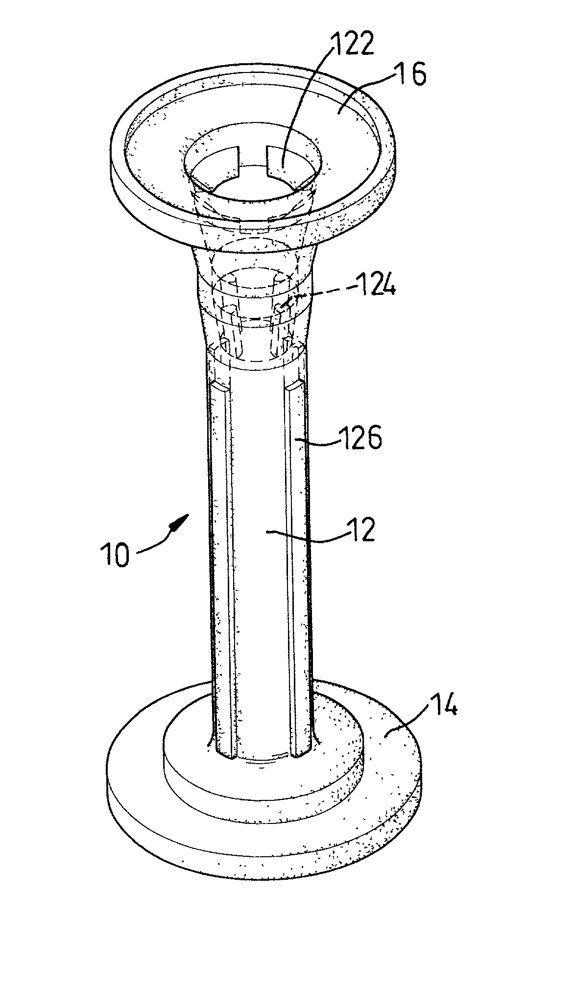
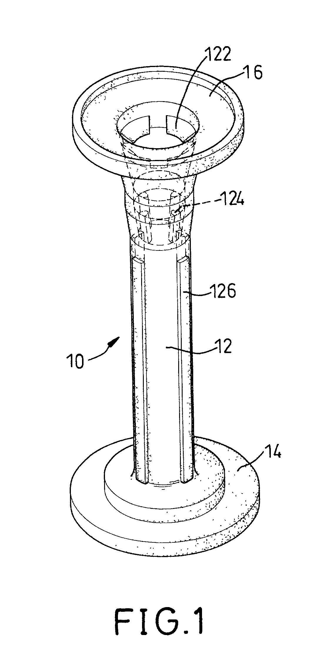
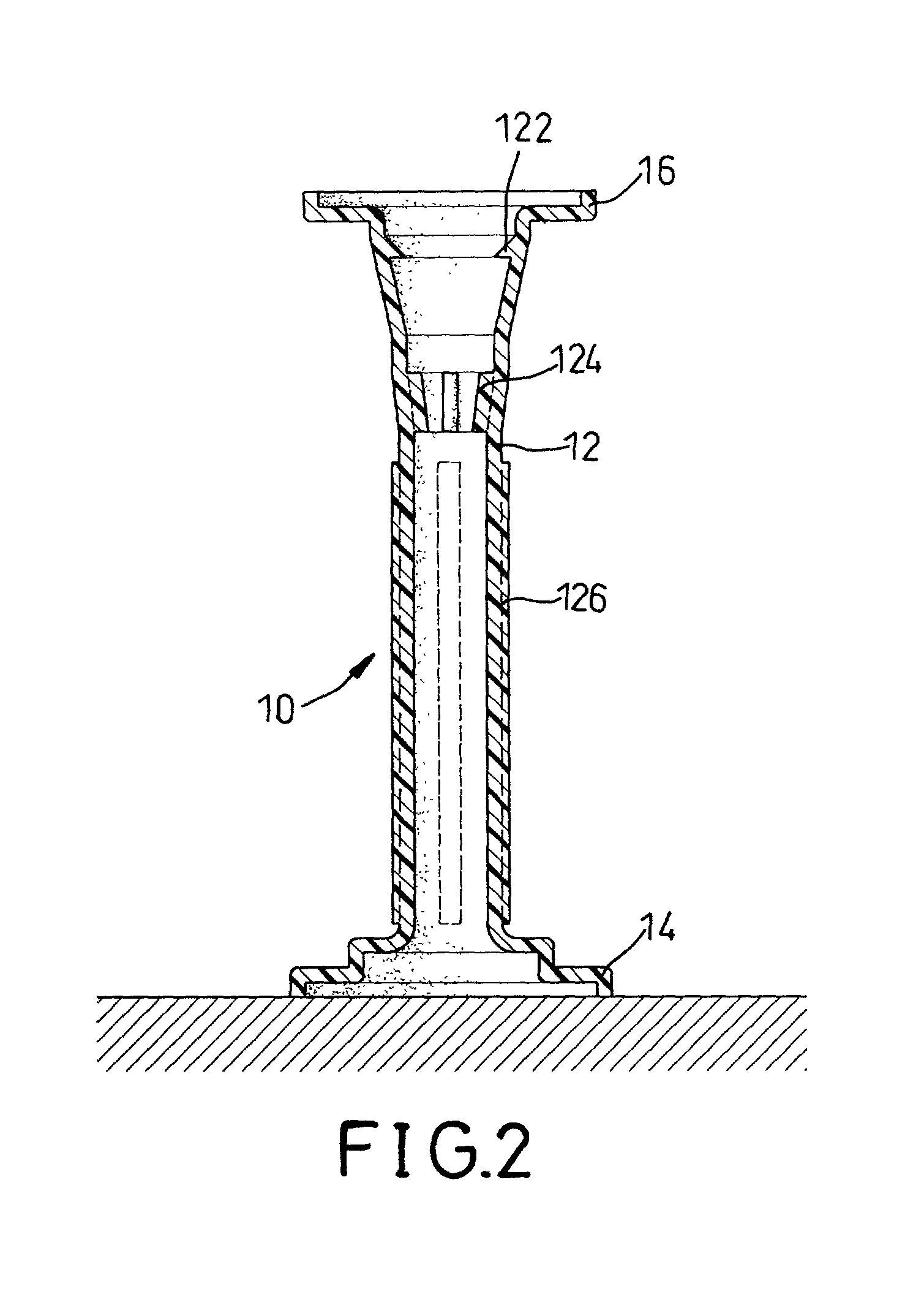
[0017] Multiple tabs (122) extend into the inside of the cap (10) from the inner periphery of the tubular body (12) at the end opposite the base (14). When the needle hub (20) is inserted into the cap (10), the tabs (122) will clamp the needle hub (20) to keep the hub (20) from escaping from the cap (10). This prevents the repeated use of the needle (22). A hood (16) extends radially out from the tubular body (12) at the end opposite to the base (14). The hood (16) serves as a guide when the needle (22) is inserted into the cap (10).
[0018] Generally, the needle hub (20) of the disposable syringe can be disengaged from the hollow barrel (24). The needle hub (20) with the needle (22) is disengaged from the hollow barrel (24) after they are inserted into the cap (10). Multiple ribs (124) are formed on the inner periphery of the tubular body (12) to engage with the needle hub (20). When the user turns the cap (10), the needle hub (20) can be released from the hollow barrel (24) by the engagement between the ribs (124) and the needle hub (20). Multiple protrusions (126) are integrally formed on the outer periphery of the tubular body (12), such that the cap (10) is easily gripped and rotated.

Problems solved by technology

However, because the user must hold the conventional cap when he or she puts the cap onto the hollow barrel, the user is easily punctured by the needle.
However, hazardous gas will form when the needle with the plastic cap and needle hub is melted or burned.
The cost for manufacturing the syringe with the conventional safety device is expensive.
In addition, because the entire syringe including the hollow barrel, plunger and the hub must be melted or burned with the needle, hazardous gas is still generated.

Method used


Image

  • Cap for a syringe
  • Cap for a syringe
  • Cap for a syringe

Examples


Embodiment Construction

[0015] With reference to FIGS. 1 and 2, a cap (10) in accordance with the present invention comprises a tubular body (12) and a base (14). The tubular body (12) has an opening defined in each end of the tubular body (12). The base (14) extends out radially from one end of the body (12) with a desired area. In practice, the base (14) is a circle. The cap (10) is able to stand upright on the base (14) on a flat object like a table.

[0016] With reference to FIGS. 2 and 3, the uses can insert the used needle (22) and the needle hub (20) of a syringe into the cap (10) standing on a table. Consequently, the used needle (22) is shielded by the cap (10), such that the used needle (22) will not puncture anyone. Because the user does not need to hold the cap (10) when the needle (22) is inserted into the cap (10), the user will not be punctured by the needle (22). The safety of disposing of used needles is improved by using the cap (10).

[0017] Multiple tabs (122) extend into the inside of the ...


PUM


Abstract

A cap has a tubular body and a base formed on one end of the tubular body. The cap can be stably stood on a flat object, such that the cap does not need to be held when the needle is inserted into the cap. The user does not need to hold the cap. The user will not be punctured. The safety of disposing of the used syringe can be improved. In addition, the needle can be punched out of the hub and drop through the opening in the cap. The plastic cap and hub does not need to be melted and burned with the needle. The generation of hazardous gas is avoided.

Description

[0001] 1. Field of the Invention[0002] The present invention relates to a cap, and more particularly to a safety cap for a syringe.[0003] 2. Description of Related Art[0004] A plastic cap is always mounted on the hollow barrel of a syringe to cover the needle to keep people from being punctured by the used needle. However, because the user must hold the conventional cap when he or she puts the cap onto the hollow barrel, the user is easily punctured by the needle. In addition, the used needle must be destroyed by melting or burning to prevent the spread of disease. However, hazardous gas will form when the needle with the plastic cap and needle hub is melted or burned.[0005] In another conventional embodiment, a safety device is formed with the syringe to prevent the user from being punctured. Clamps are formed on the needle hub and the plunger of the syringe. When the plunger is fully pushed into the hollow barrel of the syringe, the clamps will engage with each other. The needle h...

Claims


Application Information

Patent Timeline
IPC IPC(8): A61M5/32
CPCA61M5/3213A61M5/3205
Inventor SUN, WU-CHUNG
Owner SUN WU CHUNG
Learn More