Switchgear cabinet

a technology of switchgear and cabinet body, which is applied in the direction of mechanical controls, mechanical apparatus, fastening means, etc., can solve the problems of difficulty in operation and hindered access

Inactive Publication Date: 2002-07-04
RITTALWERK RUDOLF LOH GMBH & CO KG
View PDF0 Cites 15 Cited by
  • Summary
  • Abstract
  • Description
  • Claims
  • Application Information

AI Technical Summary

Problems solved by technology

Such cabinet doors are customarily locked via sliders, bolts or the like on the inside an...

Method used


Image

  • Switchgear cabinet
  • Switchgear cabinet
  • Switchgear cabinet

Examples


Embodiment Construction

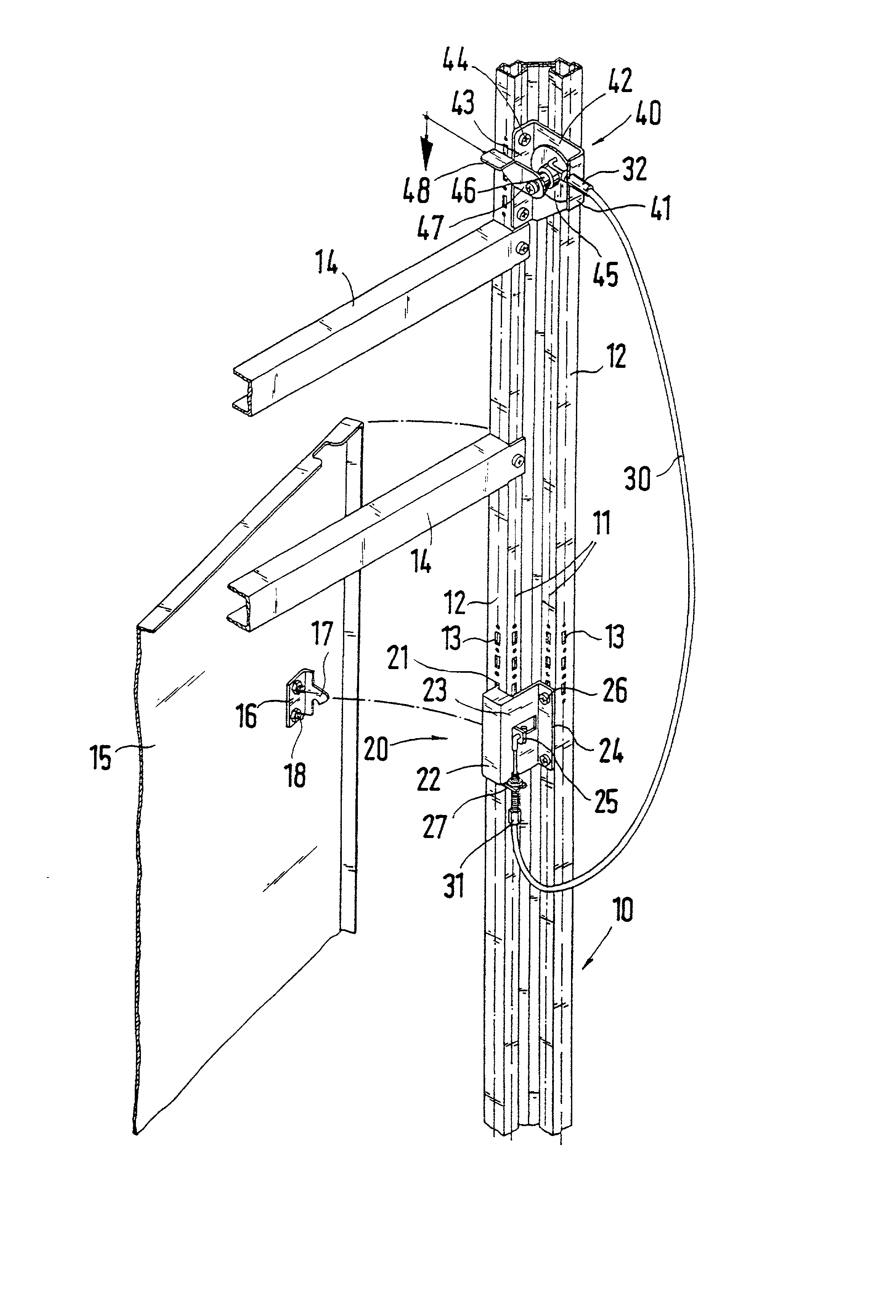
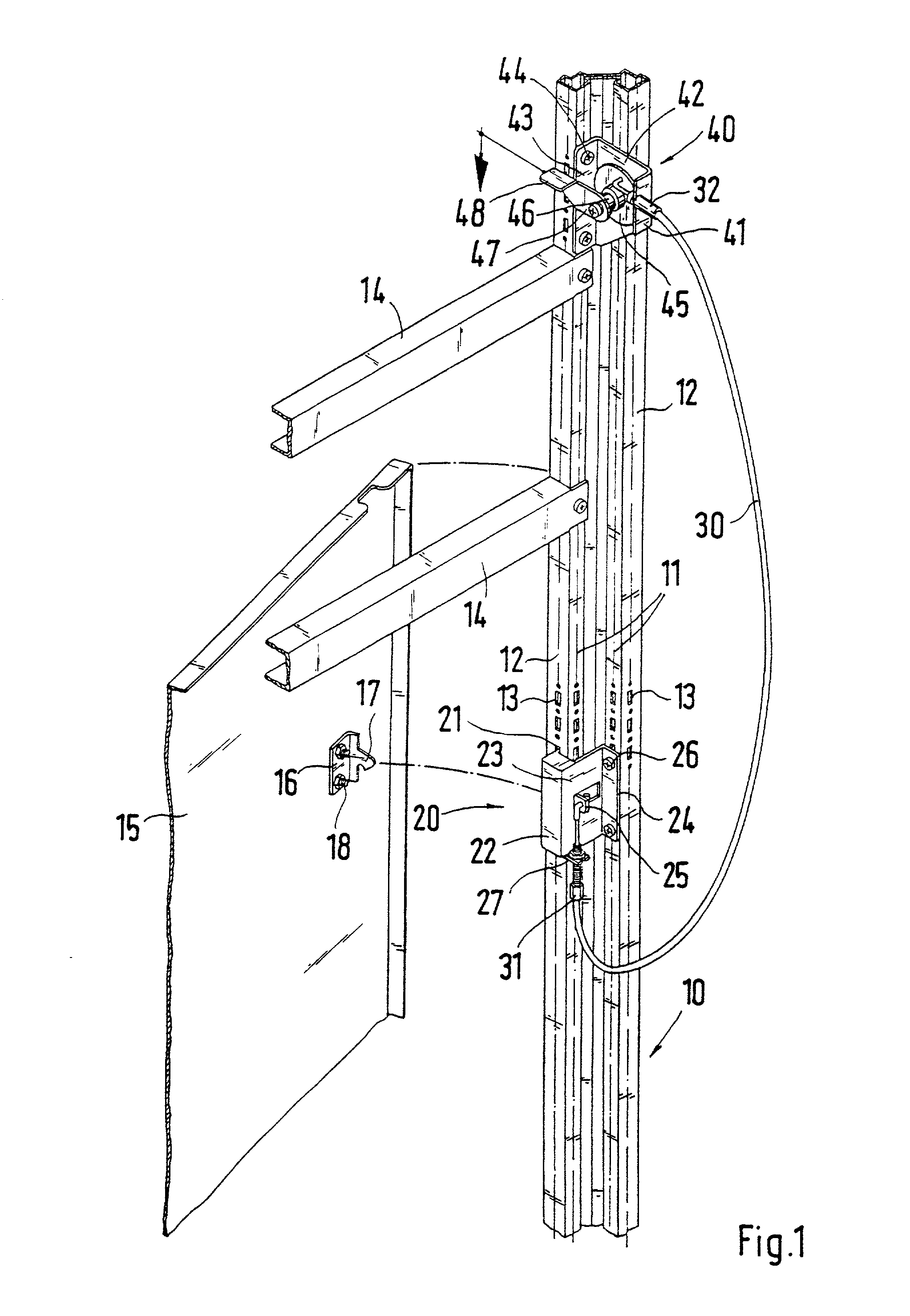
[0021] A section of a switchboard cabinet is shown in FIG. 1. The switchgear cabinet has a rack assembled from horizontal and vertical profiled frame sections 10. The vertical profiled frame sections 10 have four profiled sides 11 and 12. Each of the profiled sides 12 extends at a right angle in relation to the associated outside of the switchgear cabinet. The profiled sides 11 adjoin the profiled sides 12 at right angles and therefore extend parallel relative to the associated outsides. Each one of the profiled sides 11, 12 has a row of fastening receivers 13 preferably arranged evenly spaced apart from each other.

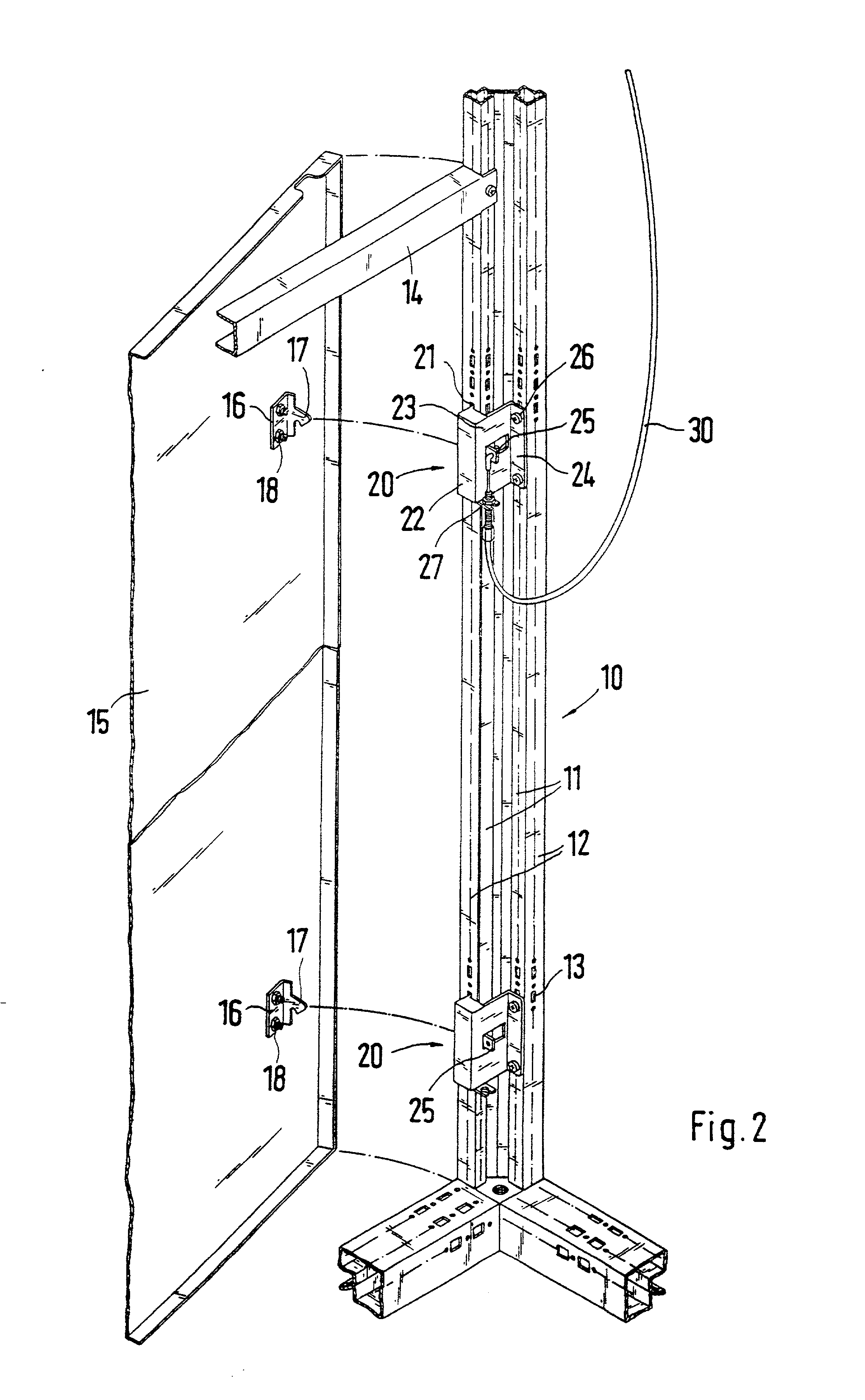
[0022] The open front of the switchgear cabinet can be closed by one or several doors 15 arranged in front of each other. Transverse struts 14 are arranged between the two vertical profiled frame sections 10 at the front.

[0023] A lock element 17 is fastened on the inside of the door 15. The lock element 17 supports a lock hook. A fastening plate 16 extends at a right angl...


PUM


Abstract

A switchgear cabinet with at least one cabinet door, which can be locked by a lock element of the switchgear cabinet body wherein, in a locked position of the cabinet door, a locking engagement between the lock element and a counter-lock element can be released by a triggering device, which is in an operative connection with the lock element or the counter-lock element via an actuating unit. So that the cabinet door can be opened in a simple way from the inside of the switchgear cabinet, the actuating unit of this invention is designed as a Bowden cable, with one end connected to the triggering device via a connecting element and an other end connected with the lock element or the counter-lock element. The triggering device has a rotatory body which is pivotably seated about an axis of rotation. The end of the Bowden cable is fastened eccentrically offset with respect to the axis of rotation on the rotatory body, and a lever with a handle is connected to the rotatory body.

Description

[0001] 1. Field of the Invention[0002] This invention relates to a switchgear cabinet with at least one cabinet door, which can be locked by a lock element of the switchgear cabinet body wherein, in the locked position of the cabinet door the locking engagement between the lock element and the counter-lock element can be released by a triggering device, which is in an operative connection with the lock element or the counter-lock element via an actuating unit.[0003] 2. Description of Related Art[0004] Such a switchgear cabinet is known from German Patent Reference DE 195 07 852 C1. A sliding bolt mechanism is attached to the inside of the cabinet door as the lock element and can be actuated from the front of the door by a handle arrangement. In the locked position of the cabinet door, the sliding bolt mechanism is in an operative connection with lock elements arranged on the switchgear cabinet. It is possible, for example, for a door to be hingedly connected with a switchgear cabine...

Claims


Application Information

Patent Timeline
IPC IPC(8): E05B53/00H02B1/38
CPCE05B53/005H02B1/38Y10T292/0992
Inventor ELM, OSKARZACHRAI, JURGENSCHAUWECKER, UWE
Owner RITTALWERK RUDOLF LOH GMBH & CO KG
Why Eureka
Try Eureka