Eureka AIR delivers breakthrough ideas for toughest innovation challenges, trusted by R&D personnel around the world.

Waterproof type lens-equipped film unit and method of assembling the same

a film unit and water-tight technology, applied in the field of water-tight film units, can solve the problems of unfavorable user operation, weak anti-reverse claw provided for the winding knob, and the possibility of the case loosening its water tightness,

Inactive Publication Date: 2002-07-18
FUJIFILM CORP
View PDF0 Cites 14 Cited by
  • Summary
  • Abstract
  • Description
  • Claims
  • Application Information

AI Technical Summary

Benefits of technology

[0016] A further object of the present invention is to make it possible to manufacture a non-flash type waterproof lf at a low cost.
[0017] Still another object of the present invention is to provide a waterproof lf that can be assembled efficiently in a watertight fashion, while preventing breakage and defects in joints between case members, and an assembling method therefor.
[0019] Because the operation button is constituted of the button portion and the mounting portion, and the button portion is fitted in the opening of the waterproof case from inside and is exposed to the outside of the waterproof case, whereas the mounting portion is force-fitted in the stepped portion that is formed around the opening on the inner wall of the waterproof case, and also because the operation member is secured by pressing the mounting portion against the inner wall of the waterproof case by means of the supporting member, the operation member is proof against the pressing operation and the water pressure, and is uneasy to remove from outside the waterproof case. Forming the supporting member integrally on the outer surface of the camera boy contributes to reducing the number of parts and the number of assembling processes, and also provides a stable support. By making the button portion protrude out of the waterproof case, and forming an outward protrusion on the edge of the opening to surround the button portion at least partly, the operation member is prevented from being pressed unexpectedly.
[0021] Even if the winding operation member is operated to rotate in the reverse direction, the second anti-reverse device stops the winding operation member from rotating reversely, so the user will notice that the winding operation member is being rotated reversely. If the winding operation member is rotated while the winding knob is locked by the stop-winding mechanism, the torque limiter disengages the winding operation member from the winding knob, so the winding operation member idles, and the stop-winding mechanism or the photo filmstrip would not be broken. Even if the winding operation member is forcibly rotated in the reverse direction to break the second anti-reverse device, because the anti-reverse device for the winding knob applies a load on the winding knob when the winding operation member is being further rotated reversely, the torque limiter releases the engagement between the winding operation member and the winding knob, so the winding operation member idles. In this way, the winding knob is securely prevented from being rotated reversely.
[0024] Since the non-flash type film unit body uses the front cover that is formed with the flash opening for exposing the light projecting portion of the flash device, and the shielding device for shielding sight of the flash opening from outside the waterproof case is provided, it becomes possible to use common parts to the flash type unit body, so the non-flash type waterproof lens-fitted photo film unit may be manufactured at a low cost. As the parts that constitute the non-flash type unit body are equal in shape and size to those used for the flash type unit body, it is possible to produce the waterproof case for the non-flash type just by applying a little modification to a flash type waterproof case. Therefore, the cost of manufacture is still more reduced.
[0025] According to another assembling method of a waterproof lens-fitted photo film unit of the present invention, the whole film unit body is covered with a pair of case members that constitute a waterproof case, and these case members are joined to each other in a watertight fashion, and thereafter an operation member, such as at least one of those members for operating a shutter mechanism, a film winding mechanism and a flash device, is coupled to the waterproof case in a watertight fashion. When the case members are water-tightly joined together, the air inside the waterproof case escapes through an opening for mounting the operation member, so the air pressure inside the waterproof case is not increased.

Problems solved by technology

However, since the operation button is mounted from the outside, it is easy to remove, so the case is likely to loose its water-tightness.
For this reason, the anti-reverse claw provided for the winding knob is too weak to securely prevent reverse rotation of the winding dial.
However, because the torque limiter as above allows the winding dial to rotate endlessly, if the user does not know much about this type of waterproof lf, the user might not notice that the winding knob is being rotated reversely, and could not take photographs.
This has been one of causes of raising manufacturing cost of the lens-fitted photo film unit.
As for the waterproof lens-fitted photo film unit, not only the film unit body but also the waterproof case need to be modified depending upon whether it is with flash or without flash, so the increase in the manufacturing cost is more remarkable.
However, when the pair of case members are water-tightly joined to each other after the operation members are mounted water-tightly, air cannot get out of the waterproof case, and is confined in the waterproof case in a compressed condition, so the air pressure inside the waterproof case gets higher.
As a result, a load is applied to joints between the case members, and sometimes breaks or loosens the joints, so the case looses its water-tightness.
For the same reason, defective products with incompletely joined case members are likely to be manufactured.

Method used


Image

  • Waterproof type lens-equipped film unit and method of assembling the same
  • Waterproof type lens-equipped film unit and method of assembling the same
  • Waterproof type lens-equipped film unit and method of assembling the same

Examples


Embodiment Construction

[0050] The present invention will be described in more detail below with reference to the accompanying drawings.

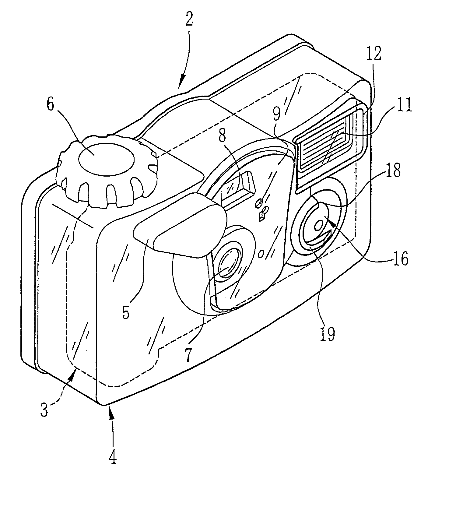
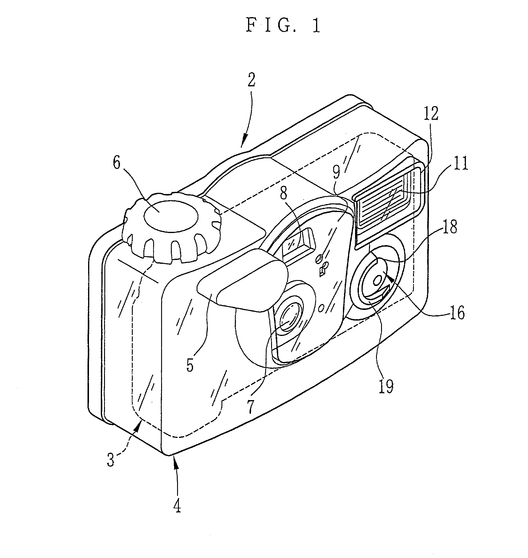
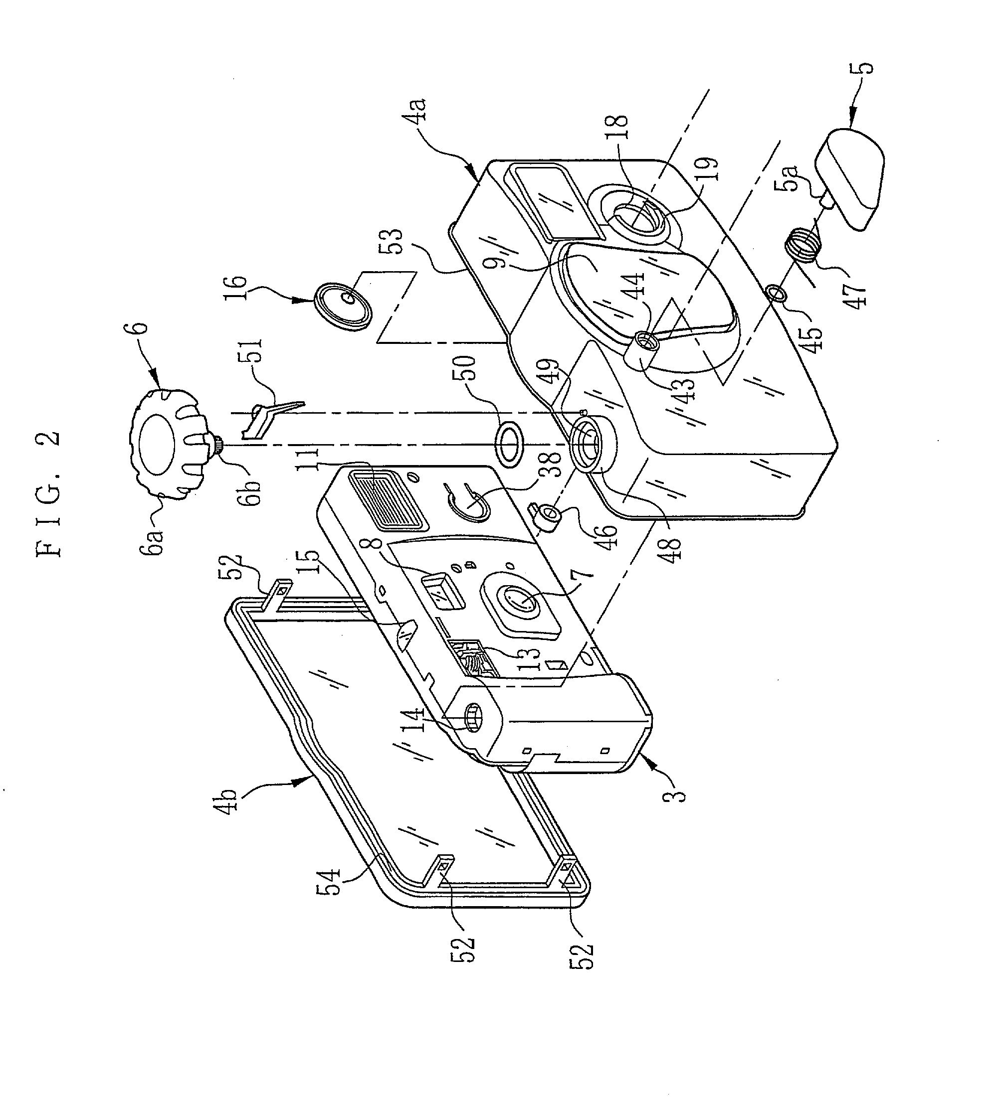
[0051] FIG. 1 is a perspective view illustrating an appearance of a waterproof lens-fitted photo film unit 2 according to a first embodiment of the present invention. The waterproof lens-fitted photo film unit 2 consists of a film unit body 3 and a waterproof case 4 that contains the film unit body 3. As shown in FIG. 2, the waterproof case 4 consists of a front case member 4a that covers front, side, top and bottom surfaces of the film unit body 3, and a rear case member 4b that covers a rear surface of the film unit body 3, and is jointed to the front case member 4a in a watertight fashion. The front and rear case members 4a and 4b are made of transparent plastic.

[0052] On outer surfaces of the waterproof case 4 are provided many kinds of operation members so that the film unit body 3 may be operated from outside the waterproof case 4. As these operation members, a windi...


PUM


Abstract

A waterproof camera includes a camera body having an actuation member that actuates an internal mechanism when pressed. A waterproof case is arranged to contain the camera body in a watertight fashion, with an opening arranged to face the actuation member and a stepped portion around the opening on an inside wall of the waterproof case. A resilient operation member having a button portion exposed to the outside through the opening has a mounting portion which fits on the stepped portion around the opening. The operation member can be resiliently deformed to press the actuation member when the button portion is depressed. A supporting member pushes the mounting portion against the stepped portion from inside the waterproof case, so as to secure the operation member. In one embodiment, the supporting member is fixed on the camera body.

Description

FIELD OF THE ART[0001] The present invention relates to a waterproof lens-fitted photo film unit that contains a body of the lens-fitted photo film unit in a watertight waterproof case to permit photographing in the water, and relates also to an assembling method therefor. More specifically, the present invention relates to a waterproof lens-fitted photo film unit that is superior in waterproof properties and handing properties, saves manufacturing cost, prevents mishandling thereof and prevents defective joints in the waterproof case, and also relates to an assembling method therefor.BACKGROUND ARTS[0002] Lens-fitted photo film units, which are preloaded with a photo filmstrip and provided with simple photographic mechanisms, are widely used in the world because of its handiness. There are a variety of lens-fitted photo film units for use in different photographic purposes and applications. For example, there are a flash type that allows photography even in the night, and a non-fla...

Claims


Application Information

Patent Timeline
Patent Type & Authority Applications(United States)
IPC IPC(8): G03B17/08
CPCG03B17/08G03B2215/0503G03B2219/045G03B17/04G03B2217/002H04N23/51
Inventor UCHIYAMA, KEIJI
Owner FUJIFILM CORP
Why Eureka
Eureka Blog
Learn More