Supercharge Your Innovation With Domain-Expert AI Agents!

Steerable load-carrying assemblies

a technology of load-carrying assemblies and steering systems, which is applied in the direction of steering parts, hand carts, transportation and packaging, etc., can solve the problems of destroying the entire exercise, not linking the castors from one side, and the mechanism involved is a complex arrangement requiring numerous parts

Inactive Publication Date: 2002-09-12
BIDWELL ALAN LESLIE
View PDF0 Cites 6 Cited by
  • Summary
  • Abstract
  • Description
  • Claims
  • Application Information

AI Technical Summary

Benefits of technology

[0068] When compared with known assemblies, the assembly of the present invention has been found to exhibit important advantages. As all wheels are mechanically linked, and are capable of being used either in fixed wheel or fully steerable modes, all the advantages associated with a fixed wheel assembly may be achieved, but without any of the inherent disadvantages--as referred to earlier in the description--being associated therewith. Furthermore, the advantages associated with four-wheel steerable assemblies are evident, again without the disadvantages. The same can be said with comparing the assembly of the present invention with known assemblies which employ four separate swivel wheel sets.

Problems solved by technology

However, there is no linkage of the castors from one side to the other.
This would defeat the entire exercise.
However, the mechanism involved is a complex arrangement requiring numerous parts, with the use of cables and links.
Furthermore, with devices such as perambulators and strollers, it is inherently intended that they not be controlled by internal forces otherwise a wriggling child or baby could control the direction of the perambulator or stroller, and this is totally contrary to what is required.

Method used


Image

  • Steerable load-carrying assemblies
  • Steerable load-carrying assemblies
  • Steerable load-carrying assemblies

Examples


Embodiment Construction

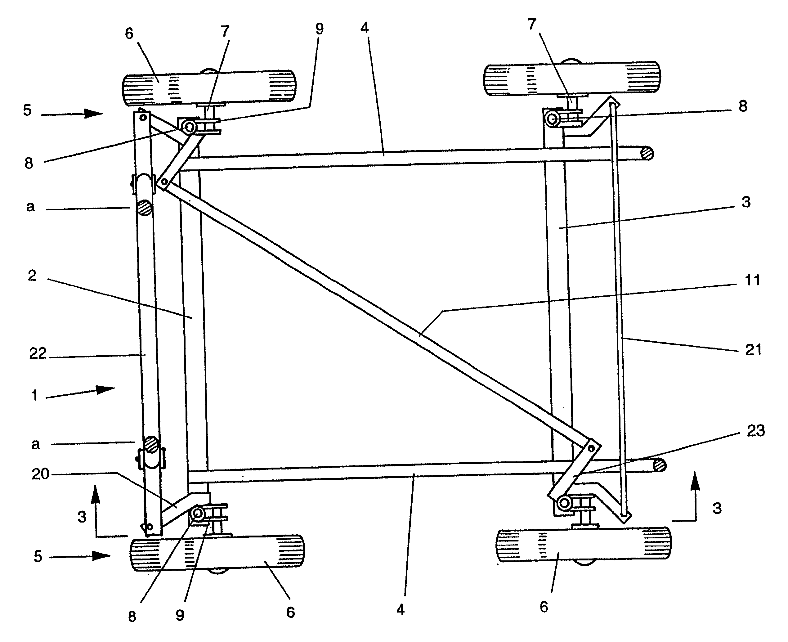
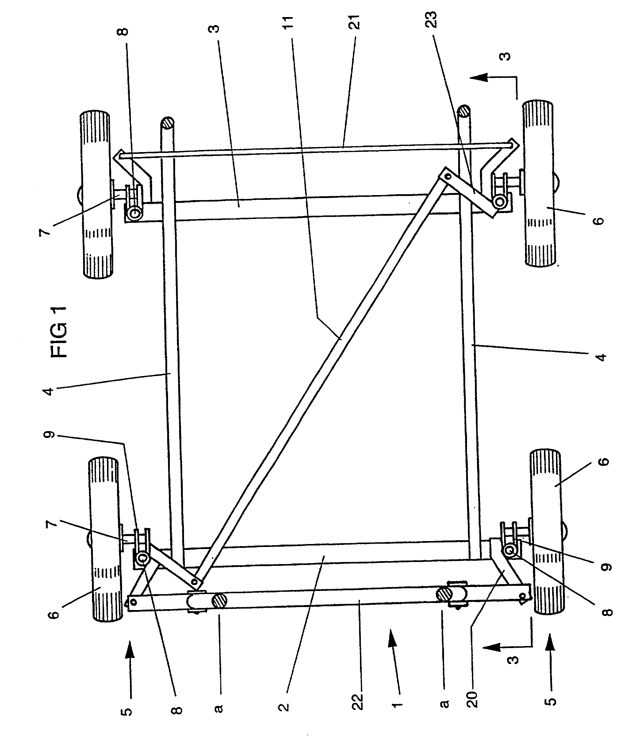
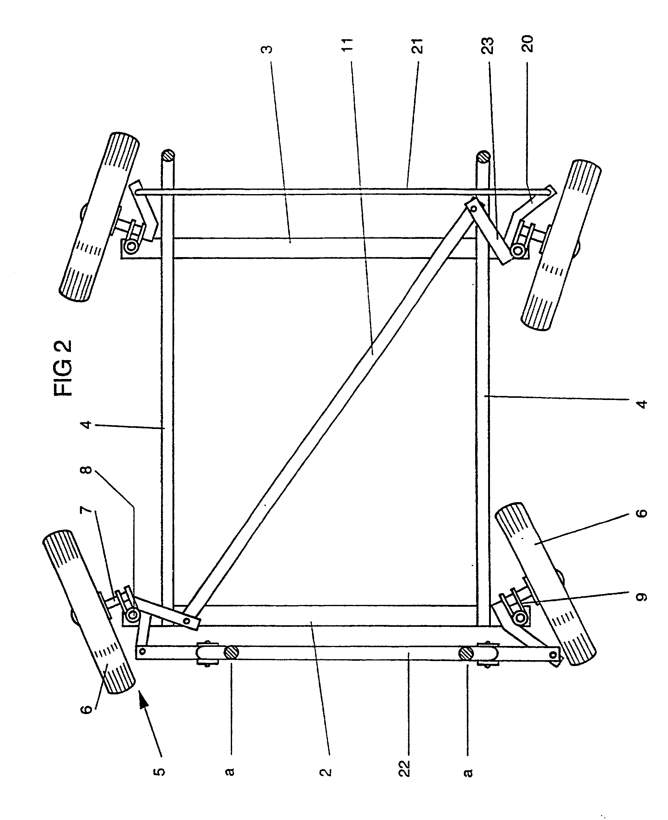
[0046] With reference now to FIGS. 1 to 3, there is illustrated a chassis made up from an interconnected arrangement of respective front and rear transverse members 2 and 3 respectively, and co-operating longitudinal members 4. The members 2, 3 and 4 make-up the chassis 1 and are inter-connected in any known manner, as for example by welding, bolting, pinning, etc., to give a substantially rigid chassis 1. As shown in FIG. 3, the members 4 are each an elongate member having a longitudinal portion 4b and, extending from the rearward end thereof, an accurate portion 4a, the accurate portions 4a being adapted, in use, to receive and preferably releasably retain a collapsible assembly which in turn is adapted to co-operate with a load-carrying means.

[0047] Mounted at or in the vicinity of each end of each of the transverse members 2, 3 are wheel assemblies 5. Wheel assemblies 5 are made up of a wheel 6, a stub axle 7 on which the wheel 6 is mounted for rotation, a swivel axle 8 fixedly ...


PUM


Abstract

A moveable load-carrying assembly including a chassis (1) having a plurality of wheels (6) arranged as a first wheel set and a second wheel set, each wheel (6) being rotatable and swivellable relative to the chassis (1); the wheels (6) of the first wheel set being connected by a first linkage (21), and the wheels (6) of the second wheel set being connected by a second linkage (22); and wherein one of the wheels (6) of the second wheel set is linked to the opposite one of the wheels (6) of the first wheel set by a link (11) such that when one of the wheels (6) of the first wheel set is swivelled in one direction relative to the chassis (1), all the wheels (6) of the first wheel set swivel in that direction in unison, and all the wheels (6) of the second wheel set swivel in the opposite direction in unison. Means are included to provide three distinct modes of operation for a wheel set, the modes corresponding to straight-line travel, fully-steerable travel and a braking mode. The assembly also includes an apparatus for returning the steerable wheels to a straight-line position, comprising a first member (203) associated with a tie rod (202) operably connected to one or more steerable wheels, at least one further member (205, 206) pivotably associated with a fixed chassis member (201) and a resilient means (209) associate with the further member.

Description

[0001] The present invention relates to improvements in moveable load-carrying assemblies and refers particularly, but not exclusively to a steerable, movable, load-carrying assembly.[0002] The present invention also includes a centralising mechanism for use with such load-carrying assemblies to assist in steering of the overall assembly.DEFINITIONS[0003] Throughout this specification reference will be made to a perambulator, pusher or push-chair for babies, invalids and the like. It should be understood that such preferred embodiments are given by way of example only and the invention is not to be considered to be limited to such usage. Indeed, the present invention will be suitable for use in any assembly intended to be propelled by human effort rather than motive power including, for example, trolleys, carts, shopping trolleys, wheel barrows, strollers, toy prams, trailers, caravans, boat trailers, wheeled jacks for vehicles, wheel chairs, gurnies, hospital beds, hospital stretch...

Claims


Application Information

Patent Timeline
Patent Type & Authority Applications(United States)
IPC IPC(8): B62D13/04B62D7/14B62B3/00
CPCB62B3/001B62B2301/06B62D13/04
Inventor BIDWELL, ALAN LESLIE
Owner BIDWELL ALAN LESLIE
Features
  • R&D
  • Intellectual Property
  • Life Sciences
  • Materials
  • Tech Scout
  • Unparalleled Data Quality
  • Higher Quality Content
  • 60% Fewer Hallucinations
Learn More