
Termination and splice panel

a technology of splicing panel and connection, which is applied in the direction of electrical apparatus casing/cabinet/drawer, furniture parts, instruments, etc., can solve the problems of insufficient space available for installing systems providing these resources, overloaded previously adequate telecommunications installations, and many facilities not designed with dedicated space. , to achieve the effect of the same footprin

Inactive Publication Date: 2002-09-12
COMMSCOPE TECH LLC
View PDF0 Cites 91 Cited by
  • Summary
  • Abstract
  • Description
  • Claims
  • Application Information

AI Technical Summary

Benefits of technology

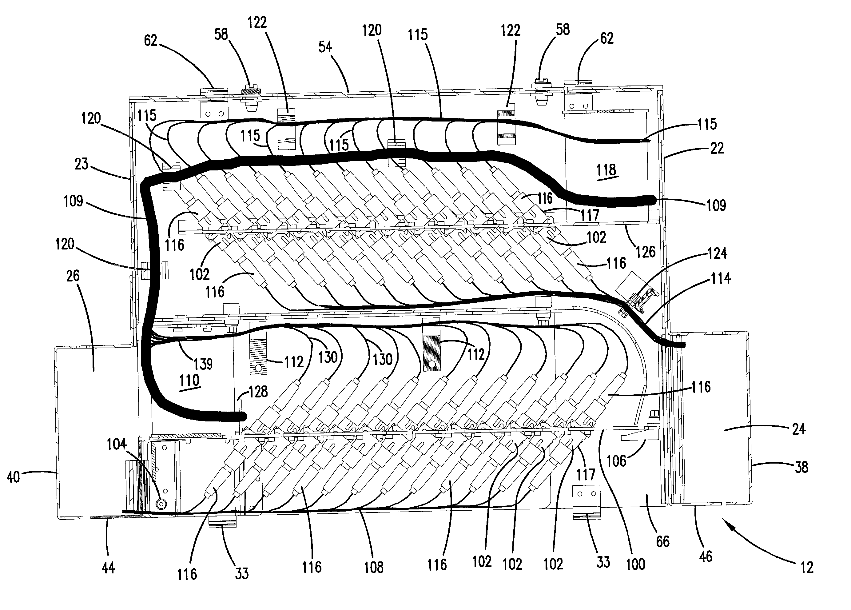
0007] A further aspect of the invention relates to splicing and high-density termination and cross-connect functions within the same system. The termination and cross-connect function are handled in a first cabinet with two bulkheads as described above. A second cabinet in the same system provides a rear cable access and cable management devices for managing the incoming and outgoing cables within the cabinet. The second cabinet has a plurality of cable splice tray storage locations for storing splice trays used to splice telecommunications cables. The first and second cabinets preferably have the same footprint and can be mounted with the first cabinet vertically above the second cabinet.

Problems solved by technology

While the demand for such resources has grown, the space available to install the systems providing these resources has not.
This growth in demand has in some cases meant that previously adequate telecommunications installations have become overloaded.
In addition, in developing regions of the world, many of the facilities were not designed with dedicated space such as is required by modern telecommunications equipment.
Existing technology available or known provides termination and connection in a single panel but not at a sufficiently high density to address the growing need for telecommunications growth.

Method used


Image

  • Termination and splice panel
  • Termination and splice panel
  • Termination and splice panel

Examples


Embodiment Construction

[0023] Reference will now be made in detail to exemplary aspects of the present invention that are illustrated in the accompanying drawings. Wherever possible, the same reference numbers will be used throughout the drawings to refer to the same or like parts.

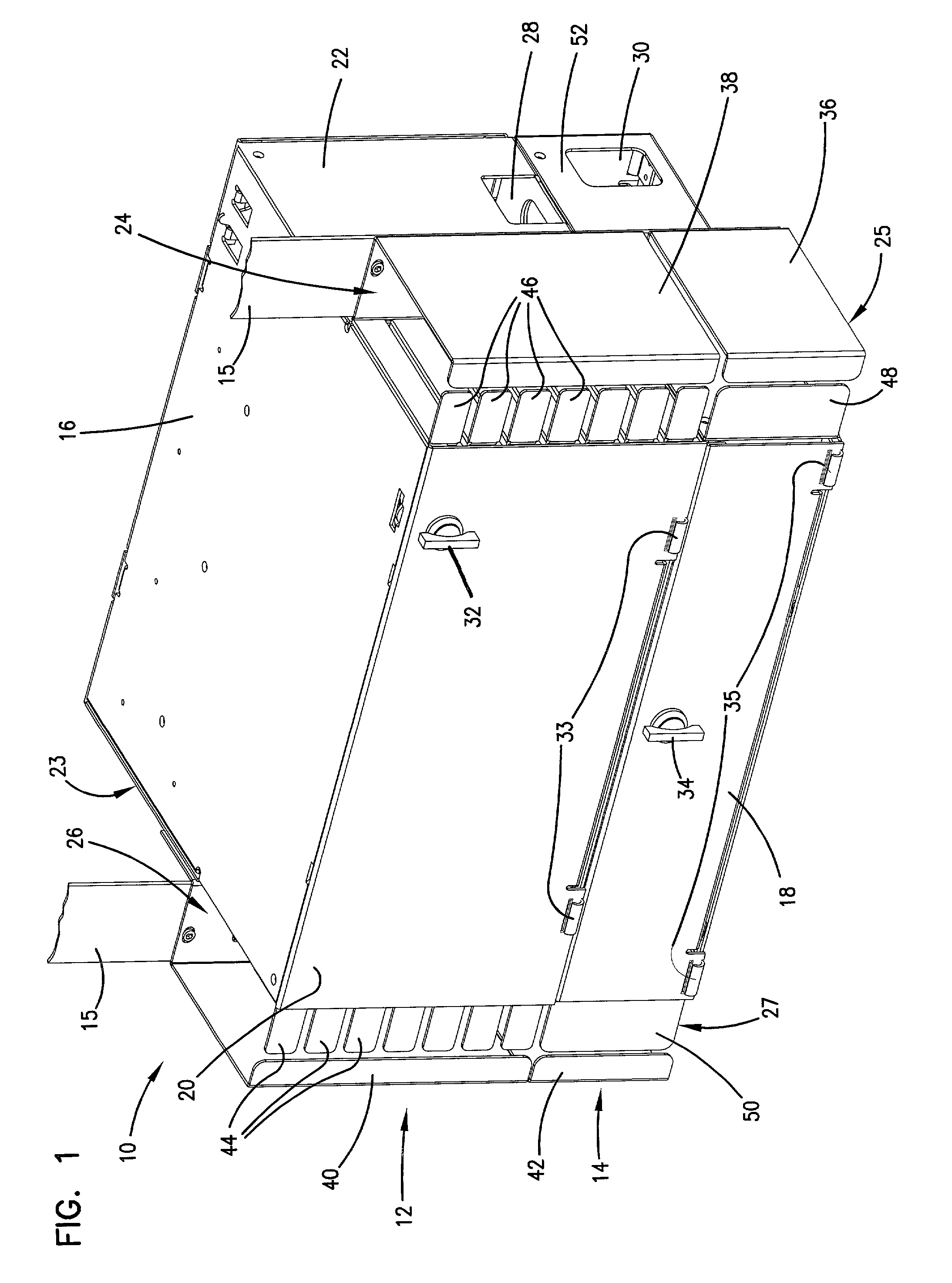
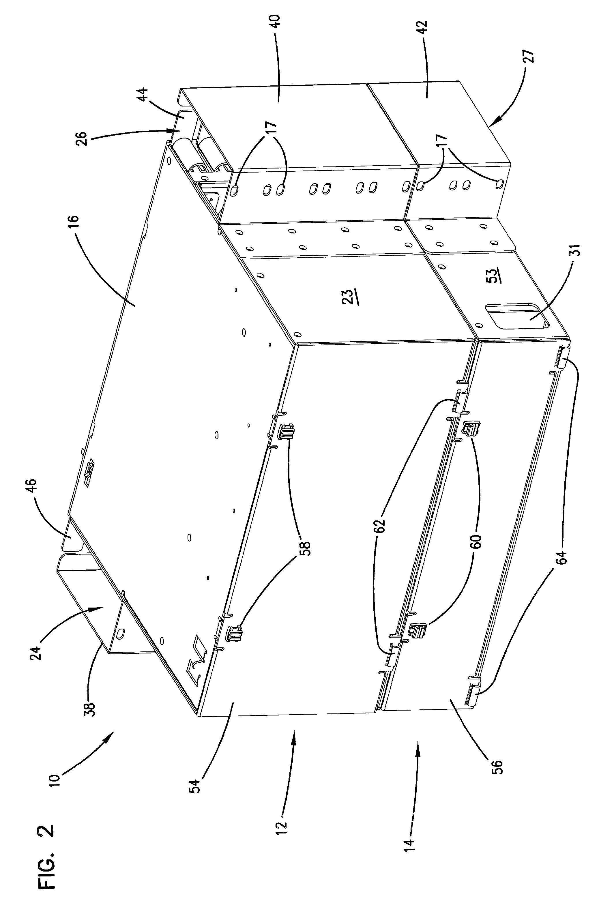
[0024] Referring now to FIG. 1, a telecommunications assembly 10 is shown, consisting of a termination cabinet 12 and a splicing cabinet 14. Cabinets 12, 14 can be mounted to a rack, frame or other support 15 through holes 17 and suitable fasteners. Termination cabinet 12 includes a top 16, two sides 22 and 23, and a front cover 20. Front cover 20 is hinged to cabinet 12 with hinges 33 and releasably held closed by a latch 32. Preferably, front cover 20 is removable from the rest of cabinet 12. On the sides of cabinet 12 are vertical cable channels 24 and 26 defined by side covers 38 and 40, movable finger guides 44 and fixed finger guides 46. Toward the rear of cabinet 12 in side 22 is rear cable opening 28.

[0025] Splicing cabi...


PUM


Abstract

A telecommunications termination cabinet includes first and second connector bulkheads, the first bulkhead located in forward position relative to the second bulkhead. The first bulkhead is pivotally mounted to the cabinet. A splice cabinet is positioned below the termination cabinet.

Description

FIELD OF THE INVENTION[0001] The present invention relates to termination, connection and splicing systems for telecommunications cables.BACKGROUND OF THE INVENTION[0002] Termination, connection and splicing systems are known in the field of telecommunications. In the recent past, there has been an explosive growth of demand for additional telecommunications paths and bandwidth. While the demand for such resources has grown, the space available to install the systems providing these resources has not. Thus, greater capabilities are being demanded which must be provided within the same physical space. This growth in demand has in some cases meant that previously adequate telecommunications installations have become overloaded. To use the same physical space for the installation of new telecommunication systems, higher density termination, connection, and splicing equipment has become apparent.[0003] In addition, in developing regions of the world, many of the facilities were not desi...

Claims


Application Information

Patent Timeline
Patent Type & Authority Applications(United States)
IPC IPC(8): G02B6/44H01R13/72H04Q1/06H04Q1/14
CPCG02B6/4452G02B6/4457H01R13/72H01R2201/16H04Q1/06H04Q2201/08H04Q2201/10H04Q2201/804H04Q1/021H04Q1/023H04Q1/026G02B6/44526G02B6/44528
Inventor KNUDSEN, CLINTON M.HENDERSON, JOHN W.HOLMAN, JOHN C.MCKNIGHT, JOY K.SMITH, TREVOR D.
Owner COMMSCOPE TECH LLC
Learn More