Radio communication apparatus

a radio communication and apparatus technology, applied in the field of digital modulation method for radio communication, can solve the problems of increasing the power consumption of the transmitting apparatus, and achieve the effect of improving the reception sensitivity characteristics of the receiving apparatus and optimal reception sensitivity of the receiving apparatus

Active Publication Date: 2002-09-12
REDWOOD TECHNOLOGIES LLC
View PDF17 Cites 41 Cited by
  • Summary
  • Abstract
  • Description
  • Claims
  • Application Information

AI Technical Summary

Benefits of technology

0006] It is an objective of the present invention to arrange pilot symbol signal points while maintaining the average transmission power of a transmitting apparatus at a fixed level, and to improve the reception sensitivity characteristics of a receiving apparatus.
0007] The present invention achieves the above objective by using a method whereby pilot symbol signal points are arranged in the in-phase-quadrature plane (IQ plane) so that the reception sensitivity of a receiving apparatus becomes optimal.

Problems solved by technology

However, with conventional pilot symbol arrangement, a signal point with the greatest signal point amplitude of signal points in one modulation method is taken as a pilot symbol signal point, but when the reception sensitivity of the receiving apparatus is considered, this point is not necessarily at the optimum position for a pilot symbol signal point.
Also, increasing the transmission power of the transmitting apparatus to improve the reception sensitivity characteristics of the receiving apparatus, and increasing the maximum signal amplitude shown in FIG. 1, means increasing the transmission power for all symbols to be transmitted, and thus increasing the power consumption of the transmitting apparatus.

Method used


Image

  • Radio communication apparatus
  • Radio communication apparatus
  • Radio communication apparatus

Examples


embodiment 1

[0047] (Embodiment 1)

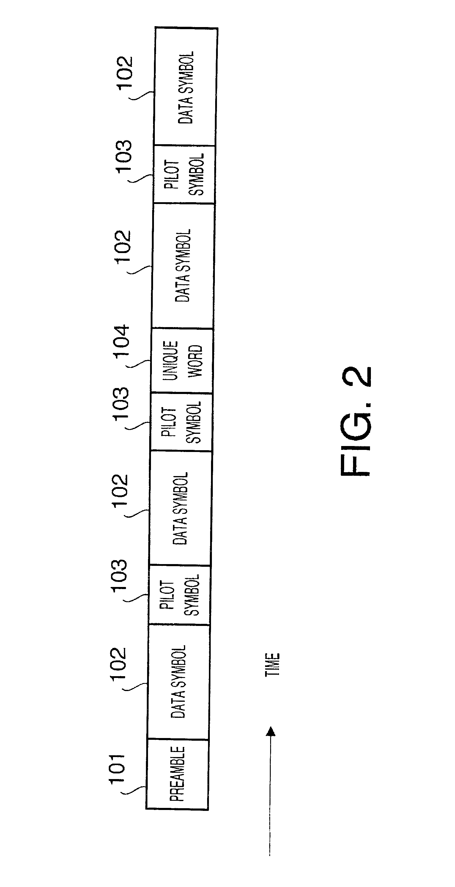
[0048] FIG. 2 shows an example of a frame configuration according to this embodiment. Modulation methods are explained below, taking a combination of three kinds--QPSK, 16QAM, and 64QAM--as an example.

[0049] In FIG. 2, a preamble 101, pilot symbols 103, and a unique word 104, are control information, and the preamble 101 includes information on the selected modulation method, including information indicating QPSK, 16QAM, or 64QAM. Data symbols 102 contain data information. The pilot symbols 103 are used to perform estimation of the radio wave propagation environment and coherent detection, and the unique word 104 is a signal for having the receiving apparatus achieve time synchronization with the transmitting apparatus. These items of control information require greater reliability than data symbols.

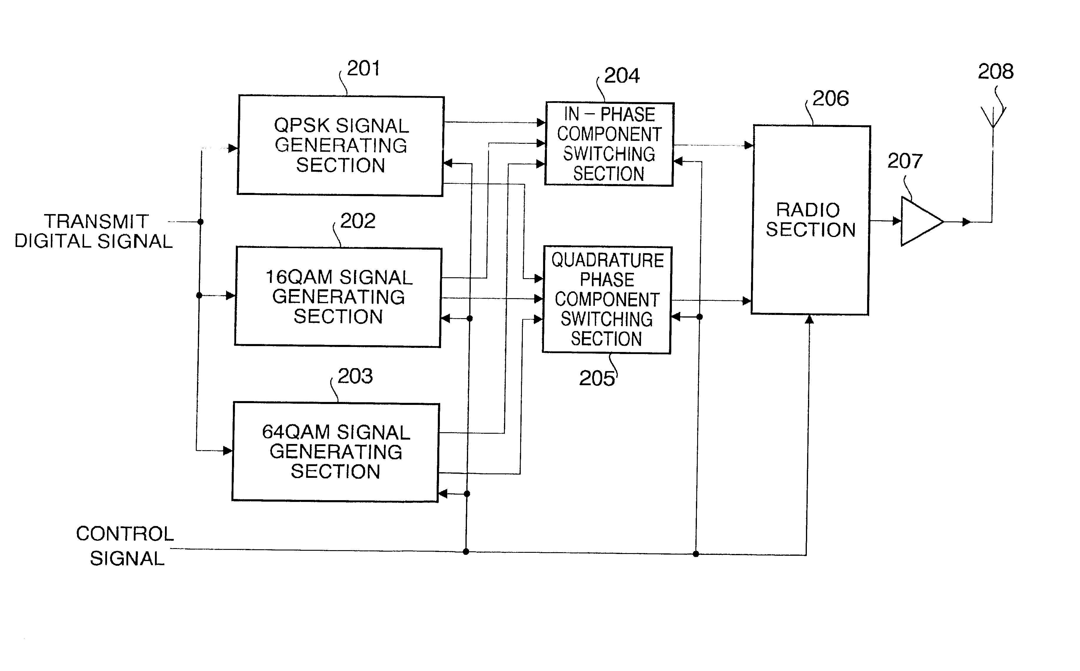
[0050] FIG. 3 shows the configuration of a transmitting apparatus according to this embodiment. In FIG. 3, in a QPSK signal generating section 201, when the modulati...

embodiment 2

[0090] (Embodiment 2)

[0091] In Embodiment 2, a communication system modulation method determination method will be described whereby the modulation method is switched according to the radio wave propagation environment and the communication traffic in a radio communication system, transmitting apparatus, and receiving apparatus using the method described in Embodiment 1.

[0092] FIG. 12 is a drawing showing an example of the frame configuration transmitted by a communication terminal according to this embodiment. The parts in FIG. 12 identical to those in FIG. 2 are assigned the same codes as in FIG. 2 and their detailed explanations are omitted. In FIG. 12, reference code 1101 denotes a preamble, containing control information. Reference code 1102 denotes radio wave propagation environment estimation information, being symbols whereby a communication terminal estimates the radio wave propagation environment of a signal transmitted by the base station, for notification to the base sta...

embodiment 3

[0132] (Embodiment 3)

[0133] In Embodiment 3, initial settings and a setting method are described for a case where the modulation method of each channel is changed adaptively according to the radio wave propagation environment, communication traffic, and so forth, in the CDMA method. At this time, a communication method is used whereby the base station primary modulation (data modulation) can be switched between QPSK modulation, 16QAM, and 64QAM, according to the radio wave propagation environment, communication traffic, and so forth.

[0134] FIG. 17 shows examples of the frame configurations of signals transmitted by a base station in the CDMA method according to this embodiment. The control channel frame is composed of channel A modulation method information 1601, channel A transmission power control information 1602, channel Z modulation method information 1603, and channel Z transmission power control information 1604. The channel A frame configuration comprises channel A data symb...


PUM


Abstract

In a radio communication method whereby adaptive modulation is performed, a method is used whereby pilot symbol signal points are arranged in the in-phase-quadrature plane (IQ plane) so that the reception sensitivity of a receiving apparatus is made optimal in the respective modulation methods while maintaining the average transmission output power of the transmitting apparatus at a fixed level. By this means, it is possible to arrange pilot symbol signal points and improve the reception sensitivity characteristics of a receiving apparatus while maintaining the average transmission output power of the transmitting apparatus at a fixed level.

Description

BACKGROUND OF THE INVENTION[0001] 1. Field of the Invention[0002] The present invention relates to a digital modulation method for use in radio communications.[0003] 2. Description of the Related Art[0004] In a digital mobile radio communication method, transmission and reception between a base station apparatus and communication terminal apparatus is influenced by the radio wave propagation environment, and the radio wave propagation environment influences reception quality and reception sensitivity characteristics on the receiving side. In this regard, heretofore, a method relating to the pilot symbol signal point position when performing quasi-coherent detection has been presented in the document (Terrestrial Mobile Communication 16QAM Fading Distortion Compensation Method) Mihei, Transactions of the Institute of Electronics, Information and Communication Engineers B-II Vol. J-72-B-II No. 1 pp. 7-15 January 1989 as a method of improving the reception sensitivity characteristics o...

Claims


Application Information

Patent Timeline
Patent Type & Authority Applications(United States)
IPC IPC(8): H04L1/00H04L27/34
CPCH04B1/0475H04B2001/0416H04B2001/045H04L1/0003H04L27/34H03F3/24H04L27/2601H04L27/3405H04L27/3494H04L2203/00H03F1/02H04L27/2082
Inventor MURAKAMI, YUTAKATAKABAYASHI, SHINICHIROABE, KATSUAKIORIHASHI, MASAYUKIMATSUOKA, AKIHIKO
Owner REDWOOD TECHNOLOGIES LLC
Why Eureka
Try Eureka