
Optical disk, reproduction apparatus, and reproduction method

a technology of optical disks and reproduction apparatuses, applied in the field of optical disks, can solve problems such as difficulty in knowing which mode of viewing/listening a user may desire, awkward reproduction of voices or sounds, and malfunction of the reproduction apparatus

Inactive Publication Date: 2002-09-12
PANASONIC CORP
View PDF0 Cites 83 Cited by
  • Summary
  • Abstract
  • Description
  • Claims
  • Application Information

AI Technical Summary

Benefits of technology

[0023] Thus, the invention described herein makes possible the advantages of (1) providing an optical disk capable of switching, in accordance with various modes of viewing / listening as desired by a user, between exclusive reproduction of audio information and reproduction of both video information and audio information without the creation of malfunctions, as well as an apparatus and a method for reproducing such an optical disk; and (2) providing an optical disk which allows the reproduction or playback of higher-quality audio information during audio reproduction than during video reproduction, as well as an apparatus and a method for reproducing such an optical disk.

Problems solved by technology

In the case of applications of image-accompanied music, it is difficult to know which mode of viewing / listening a user may desire because one user may wish to only listen to the music without viewing the images, while another may wish to enjoy both the music and the images.
However, in the case of playback of only the audio information of an image-accompanied music application, merely omitting the image information reproduced from the image-accompanied music application from display may result in an awkward reproduction of those voices or sounds which would only be meaningful when reproduced along with images, e.g., the voices and sounds of an interview in an music clip.
Furthermore, merely omitting from display the image information reproduced from the image-accompanied music application may result in a malfunctioning of the reproduction apparatus due to the omission of the images.

Method used


Image

  • Optical disk, reproduction apparatus, and reproduction method
  • Optical disk, reproduction apparatus, and reproduction method
  • Optical disk, reproduction apparatus, and reproduction method

Examples


example 1

[0075] Hereinafter, the structure of an optical disk according to one example of the present invention will be described.

[0076] (1) Physical structure of the optical disk

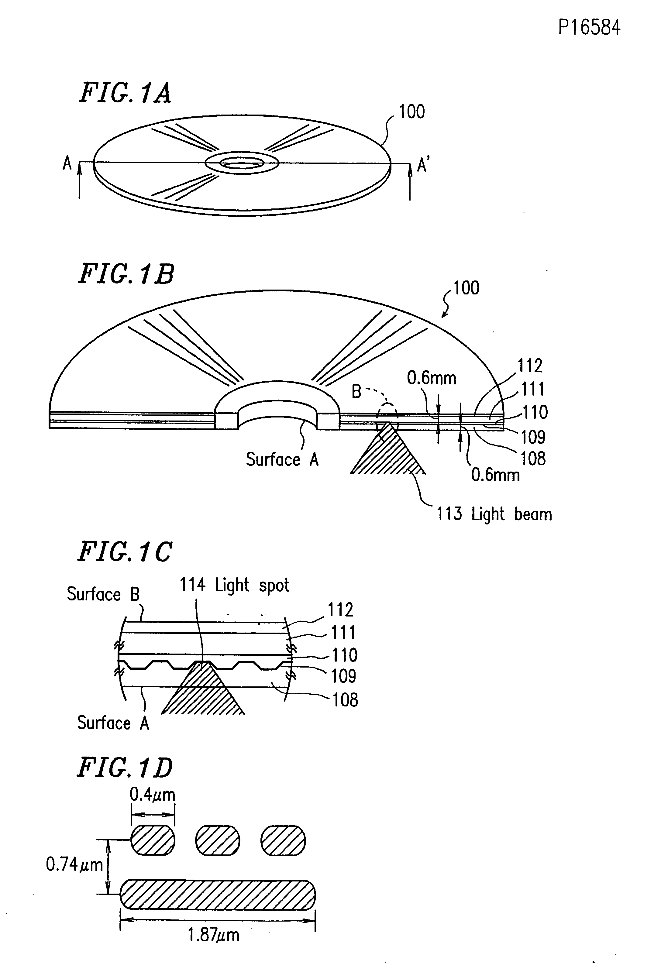
[0077] FIG. 1A is a perspective view showing a DVD 100, which is one type of optical disk. FIG. 1B is a cross-sectional view of the DVD 100 taken along line A-A' in FIG. 1A. FIG. 1C is an enlarged cross-sectional view of portion B shown in FIG. 1B.

[0078] As shown in FIG. 1B, the DVD 100 is formed by laminating a first transparent substrate 108, an information layer 109, an adhesive layer 110, a second transparent substrate 111, and a print layer 112 (on which a label is to be printed) in this order.

[0079] The first transparent substrate 108 and the second transparent substrate 111 are reinforcement substrates that are formed of the same material. In the example shown in FIG. 1B, these substrates each have a thickness of about 0.6 mm. These substrates can each have a thickness in the range between about 0.5 mm and ab...

example 2

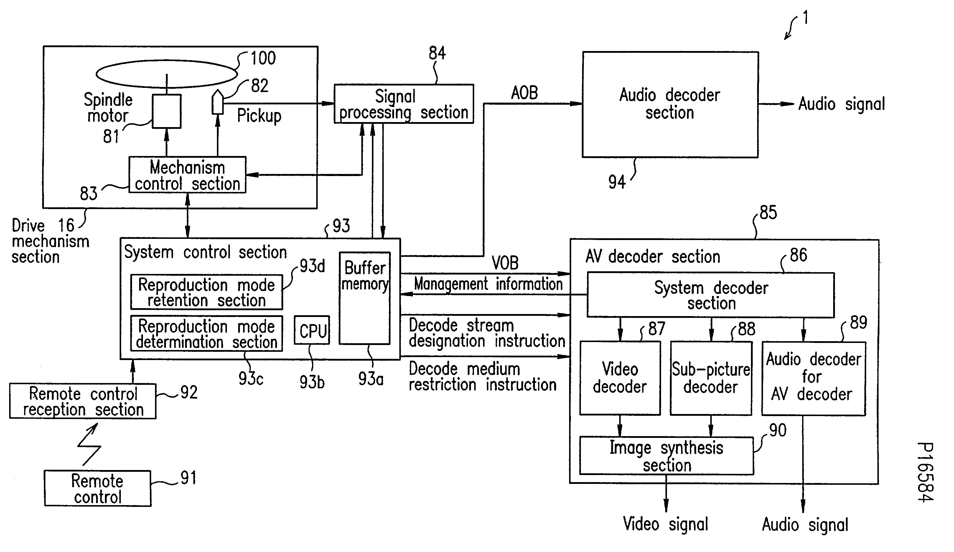
[0312] Hereinafter, the reproduction by an audio player with video functions will be described. The structure of an audio player with video functions is the same as that of the DVD player 1 shown in FIG. 12 except that the audio player with video functions is arranged so that the determination as to whether the reproduction mode is going to be a video-oriented reproduction mode or an audio-oriented reproduction mode is not performed before a reproduction process. The audio player with video functions is defined as an audio player which is specially designed for audio purposes but additionally has an image displaying function.

[0313] FIG. 19 shows the flow of a reproduction process by the audio player with video functions.

[0314] At step S191, it is determined whether or not an optical disk is loaded in the audio player with video functions. Such determination can be performed in accordance with, for example, a signal from an optical sensor.

[0315] If it is determined that an optical di...

example 3

[0335] Hereinafter, an optical disk that allows switching of the audio information to be reproduced depending on the audio reproducing capabilities of the reproduction apparatus, as well as an apparatus and a method for reproducing the same, will be described.

[0336] The structure of the reproduction apparatus of the present example is the same as that of the DVD player 1 shown in FIG. 12 except that the reproduction apparatus of the present example is arranged so that the determination as to whether the reproduction mode is going to be a video-oriented reproduction mode or an audio-oriented reproduction mode is not performed before a reproduction process. The reproduction apparatus of the present example is defined as an audio player which is specially designed for audio purposes.

[0337] The data structure stored on the optical disk is the same as the data structure stored on the optical disk according to Example 1.

[0338] FIG. 21A shows exemplary data to be stored on the optical disk...


PUM

PropertyMeasurementUnit
diameteraaaaaaaaaa
diameteraaaaaaaaaa
lengthaaaaaaaaaa

Abstract

An optical disk includes: a data region; and a management region. The data region stores: at least one video object containing video information and audio information; and at least one audio object containing audio information. The management region stores first path information and second path information, the first path information indicating a first reproduction path including only the at least one video object, and the second path information indicating a second reproduction path including a combination of the at least one video object and the at least one audio object.

Description

BACKGROUND OF THE INVENTION[0001] 1. Field of the Invention[0002] The present invention relates to an optical disk for storing digital data of multimedia data including audio information and moving image information that are associated with each other, as well as an apparatus and a method for reproducing the same.[0003] 2. Description of the Related Art[0004] Conventionally, CDs (compact disks) and LDs (laser disks) are known as optical disks for storing and reproducing audio information and / or moving image information.[0005] A CD is an optical disk having a diameter of 12 cm. A CD carries audio information stored thereon which has been quantized by using a linear PCM method. CDs are widely prevalent as a storage medium for music-oriented applications.[0006] An LD is an optical disk having a diameter of 30 cm. An LD carries moving image information stored thereon in the form of analog signals. LDs are widely prevalent as a storage medium for image-oriented applications such as movie...

Claims


Application Information

Patent Timeline
Patent Type & Authority Applications(United States)
IPC IPC(8): G11B7/007G11B19/02G11B20/10G11B20/12H04N5/85G11B27/00G11B27/10G11B27/11G11B27/30G11B27/32G11B27/34H04N5/775H04N9/804H04N9/806H04N9/82
CPCG11B19/02H04N9/8227G11B20/1217G11B20/1251G11B27/105G11B27/11G11B27/3027G11B27/309G11B27/329G11B27/34G11B2020/10592G11B2220/211G11B2220/213G11B2220/2562G11B2220/65H04N5/775H04N5/85H04N9/8042H04N9/8063G11B20/10527B60R11/0211G11B2020/1232G11B2220/2537
Inventor MORI, YOSHIHIROKOZUKA, MASAYUKIYAMAUCHI, KAZUHIKO
Owner PANASONIC CORP
Learn More