Compressor diagnostic and recording system

a compression engine and recording system technology, applied in the direction of positive displacement liquid engines, lighting and heating apparatuses, liquid fuel engines, etc., can solve the problem of memory being over a very long period of tim

Inactive Publication Date: 2002-09-12
HAHN GREG +7
View PDF0 Cites 94 Cited by
  • Summary
  • Abstract
  • Description
  • Claims
  • Application Information

AI Technical Summary

Benefits of technology

0007] In a disclosed embodiment of this invention, a control receives signals relating to a number of operational factors in a compressor. Preferably, the discharge temperature and pressure, the suc

Problems solved by technology

As an example, if one of the sensed temperatures is gradually increasing over time, this may be indicative of a "slow leak" in

Method used


Image

  • Compressor diagnostic and recording system
  • Compressor diagnostic and recording system
  • Compressor diagnostic and recording system

Examples


Embodiment Construction

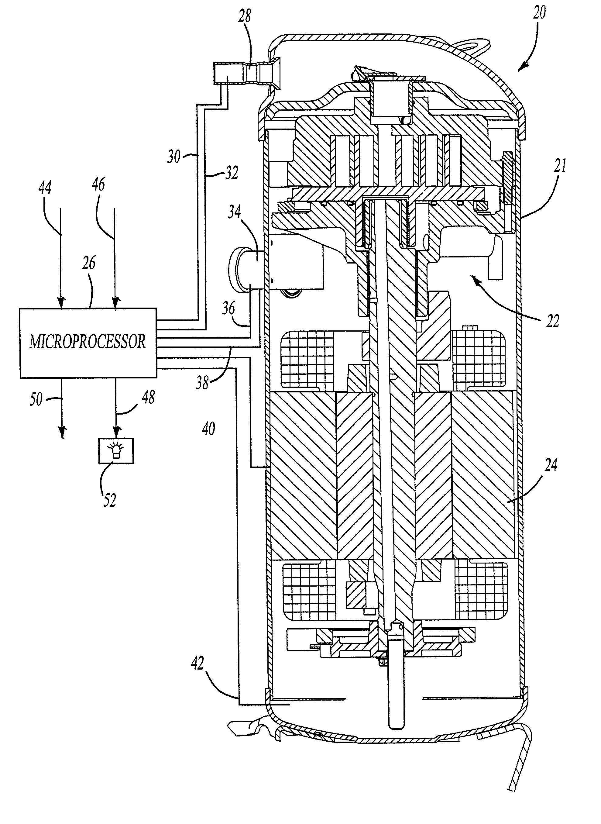
[0015] A sealed compressor 20 is illustrated in FIG. 1. It should be understood that compressor 20 is received within a sealed housing 21, and is preferably incorporated into a refrigerant cycle, such as are typically found in air conditioning or other cooling cycles.

[0016] A compressor pump unit 22 is shown as a scroll compressor. A motor 24 drives compressor pump unit 22. A control 26 receives a number of signals on operation of the compressor. As shown, all of the signals can be taken from external locations in the compressor. As an example, a discharge tube 28 can be provided with a temperature sensor 30 and a pressure sensor 32. The outputs of the sensors 30 and 32 are delivered to the control 26. A suction tube 34 can be provided with a suction temperature sensor 36 and a suction pressure sensor 38. A control line 40 to the motor can be operable to stop operation of the motor. A sump temperature sensor 42 can be positioned adjacent a lower end of the housing 21, where it will ...


PUM


Abstract

A compressor diagnostic system incorporates a control which receives a plurality of data streams about various operational features of the compressor. As an example, both temperature and pressure of the suction and discharge refrigerant are taken and sent to the control. Moreover, information with regard to the power being supplied to the motor is taken and stored. All of this information is utilized at a control which compares the information to expected values and determines a fault based upon the evaluation. Moreover, in another feature of this invention, much of this data is stored, and maintained at the compressor. In the event of a compressor failure, this stored information will provide a maintenance worker with a good indication of why the compressor failed.

Description

[0001] This application is a divisional of U.S. patent application Ser. No. 09 / 553,836, filed Apr. 21, 2000.BACKGROUND OF THE INVENTION[0002] This invention relates to a system which interprets compressor operational factors, and monitors these factors to identify irregularities. Moreover, the system stores the factors, thus providing a record.[0003] Compressors are utilized to compress a refrigerant as part of a refrigerant cycle in cooling systems. Modem compressors for refrigerant compression are typically enclosed in a sealed housing. The compressors are driven by a motor which is driven by a single phase or a three phase power supply. Compressors operate under many extreme conditions. Some compressors have relatively complex operational parts. In one popular modem type compressor, two spiral scroll wraps orbit relative to each other to compress entrapped refrigerant. While scroll compressors are gaining wide popularity, they also are subject to design challenges. As an example,...

Claims


Application Information

Patent Timeline
IPC IPC(8): F04C18/02F04C23/00F04C28/06F04C28/28F25B1/04F25B49/00
CPCF04C18/0207F04C23/008F04C28/06F04C28/28F04C2240/603F25B1/04F25B49/005F25B2700/1931F25B2700/1933F25B2700/21151F25B2700/21152F04C2240/803F04C2240/81F04C2270/80
Inventor HAHN, GREGSUN, ZILIZAMUDIO, CARLOSHUGENROTH, JASONBARITO, THOMASBUSH, JAMES W.HILL, JOE T.WILLIAMS, JOHN R.
Owner HAHN GREG
Why Eureka
Try Eureka