AC-adapter and pin configuration adapter for AC-adapter

a technology of pin configuration and ac adapter, which is applied in the direction of coupling device details, electrical discharge lamps, coupling device connections, etc., can solve the problems of troublesome preparation of ac adapters of different pin configurations conforming to domestic and foreign standards, and comparatively expensive preparation of different types of ac adapters

Inactive Publication Date: 2002-09-12
MITSUMI ELECTRIC CO LTD
View PDF0 Cites 33 Cited by
  • Summary
  • Abstract
  • Description
  • Claims
  • Application Information

AI Technical Summary

Benefits of technology

0020] With the combination described above, the AC-adapter is prevented from being detached from the pin-configuration adapter when retracting the combination from the power socket. Each of the engagement groove may include a first engagement groove part and a se...

Problems solved by technology

However, there is no global standard configuration for a power socket, and therefore there are various configuration of the power socket for various countries.
However, it is troublesome to prepare AC-adapters of different pin configurations conforming to the domestic standard and to foreign standards.
Also, since each of the AC-adapters has a conversion circuit therein, it is comparatively expensive to prepare different types of AC-adaptors.
Therefore, it is an economic burden...

Method used


Image

  • AC-adapter and pin configuration adapter for AC-adapter
  • AC-adapter and pin configuration adapter for AC-adapter
  • AC-adapter and pin configuration adapter for AC-adapter

Examples


first embodiment

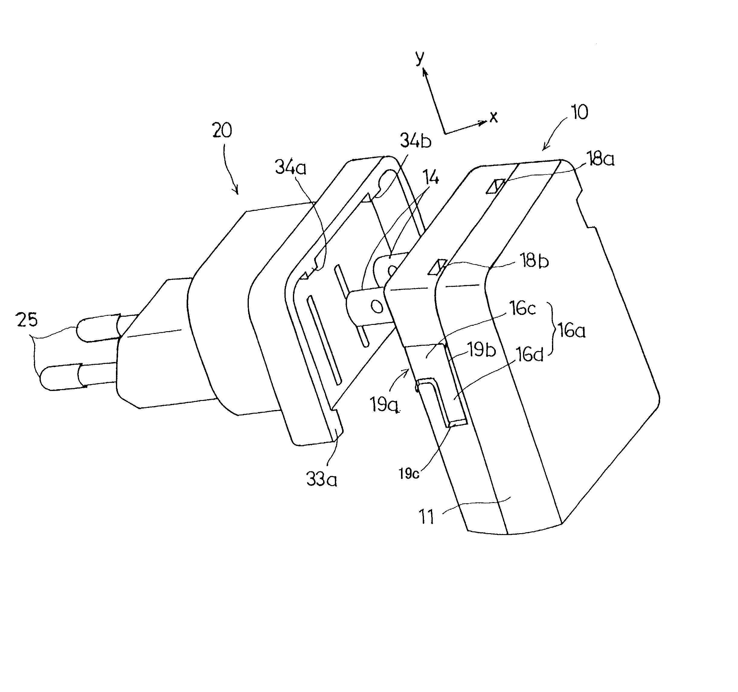
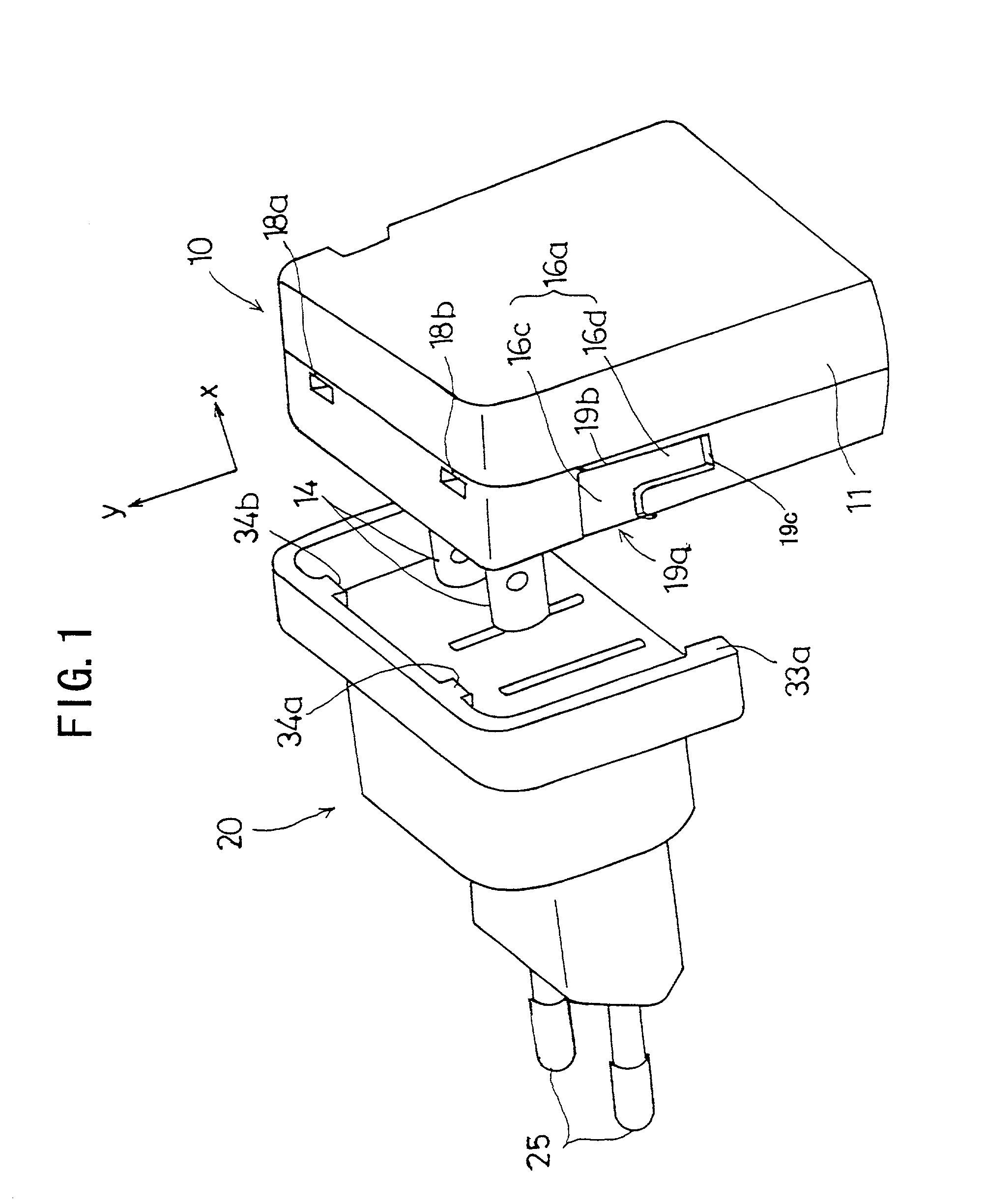
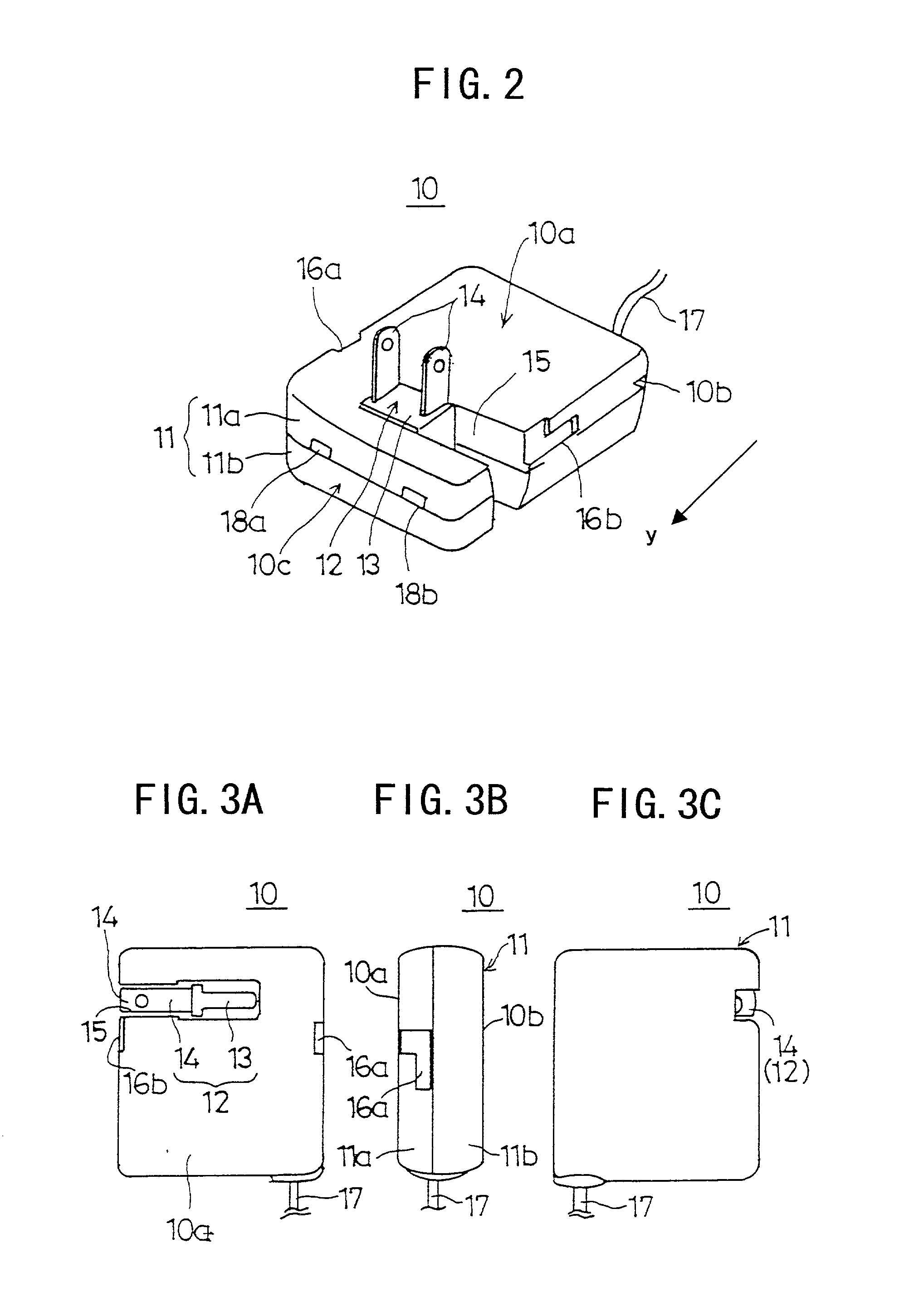
[0034] FIGS. 1 to 7 are diagrams used for explaining a pin configuration adapter for an AC-adapter (hereinafter referred to as a pin configuration adapter) 20 of a first embodiment the present invention. FIG. 1 is a diagram showing how the pin configuration adapter 20 is attached to an AC-adapter 10. FIG. 2 is a perspective view of the AC adapter 10. FIGS. 3A through 4C are diagrams showing the configuration of the AC-adapter 10. FIGS. 5A through 5C are diagrams showing the structure of the pin-configuration adapter 20. FIGS. 6A and 6B are diagrams showing how the pin-configuration adapter 20 is attached to the AC-adapter 10.

[0035] As shown in FIG. 1, in use, the pin configuration adapter 20 is attached to the AC-adapter 10.

[0036] Before describing the pin configuration adapter 20 in detail, an explanation will be made of the AC-adapter 10. As shown in FIG. 2, the AC-adapter 10 generally includes an AC-adapter housing 11, a rotatable plug body 12 and a cord 17.

[0037] The adapter hou...

second embodiment

[0069] In the following, the present invention will be described.

[0070] FIGS. 8 through 11 are diagrams used for explaining the second embodiment of the present invention.

[0071] FIG. 8 is a perspective view showing how a pin configuration adapter 120 is attached to an AC-adapter 110 in accordance with a second embodiment of the present invention. FIGS. 9A through 9C are diagrams showing a structure of the AC-adapter 110 of the second embodiment of the present invention. FIGS. 10A through 10D are diagrams showing a plug configuration adapter 120 of the second embodiment of the present invention.

[0072] As shown in FIG. 8, when in use, the pin configuration adapter 120 is attached to the AC-adapter. This is similar to the case of the first embodiment.

[0073] Before explaining the pin configuration adapter 120, the structure of the AC-adapter 110 will be described. Elements similar to those of the first embodiment are labeled using the same reference numerals and will not be explained in...


PUM


Abstract

A combination includes an AC-adapter and a pin configuration adapter. The AC-adapter includes a plug body having first pins of a first configuration and an AC-adapter housing having a conversion circuit for converting an electric power supplied via the plug body. The pin configuration adapter includes a plug part having second pins of a having configuration different from the first pin configuration, a receptacle part whereto the first pins can be inserted and a pin configuration adapter housing having an internal connection mechanism for electrically connecting the plug body and the plug part. The AC-adapter is provided with engagement grooves which engage with protrusions provided on said pin configuration adapter.

Description

BACKGROUND OF THE INVENTION[0001] 1. Field of the Invention[0002] The present invention relates to a pin configuration adapter for an AC-adapter, and particularly relates to a pin configuration adapter having a different pin type from that of the AC-adapter and which is, in use, attached to the AC-adapter.[0003] 2. Description of the Related Art[0004] Generally, a power transformer (AC-adapter) is widely used for supplying power to portable electronic devices and / or for recharging batteries of such electronic devices. The power transformer includes a housing, a plug protruding from the housing, a conversion circuit provided inside the housing and an output cord extending from the housing. In order to plug the power adapter to the power socket, the pins are inserted into the power socket. In the converting circuit, an alternating current supplied from the power socket is converted to a direct current of a predetermined voltage. The obtained direct current is output from the output co...

Claims


Application Information

Patent Timeline
IPC IPC(8): H01R13/46H01R13/639H01R13/627H01R31/06
CPCH01R13/6273H01R31/06
Inventor KAJIWARA, TERUTOMOKINKAWA, TAKENORIHAMAI, HIDETOSHI
Owner MITSUMI ELECTRIC CO LTD
Why Eureka
Try Eureka