Apparatus and method for defragmentation in disk storage system

a disk storage system and disk storage technology, applied in the field of disk storage systems, can solve the problems of affecting the performance of the host system, and the inability to input/output data between the host system and the hdd

Inactive Publication Date: 2002-09-12
KK TOSHIBA
View PDF2 Cites 26 Cited by
  • Summary
  • Abstract
  • Description
  • Claims
  • Application Information

AI Technical Summary

Benefits of technology

0013] According to an aspect of the invention, there is provided a disk storage system for writing data to a disk medium and reading data from the disk medium. This system comprises fragmentation determining means and controlling means. The fragmentation determining means determines, when a host system has requested the disk storage system to read temporally-sequenced data, whether the temporally-sequenced data is fragmented into a plurality of data blocks on the disk medium. The controlling means executes the control of writing the temporally-sequenced data read from the disk medium to a contiguous area on the disk medium, in parallel with the execution of the control of reading the temporally-sequenced data from the disk medium and transferring the read temporally-sequenced data to the host system, if the fragmentation determining means determines that the temporally-sequenced data is fragmented.

Problems solved by technology

When an unnecessary section of AV data has been cut by editing, fragmentation of data always occurs, which degrades the performance of the AV-HDD.
This technique, however, inevitably involves a degradation of the performance of the host system, although it can prevent a degradation of the performance of the HDD.
Moreover, in this technique, during the time defragmentation is executed, input / output of data for, for example, reproduction of an AV stream cannot be executed between the host system and the HDD.
In this case, however, data still cannot be input / output between the host system and the HDD during the time defragmentation is executed.
However, during the time defragmentation is executed, input / output of data for, for example, reproduction of an AV stream cannot be executed between the host system and the HDD as in the prior art.
Furthermore, the reading performance of occasional-use AV data is as low as in the prior art.

Method used


Image

  • Apparatus and method for defragmentation in disk storage system
  • Apparatus and method for defragmentation in disk storage system
  • Apparatus and method for defragmentation in disk storage system

Examples


first embodiment

[0028] [First Embodiment]

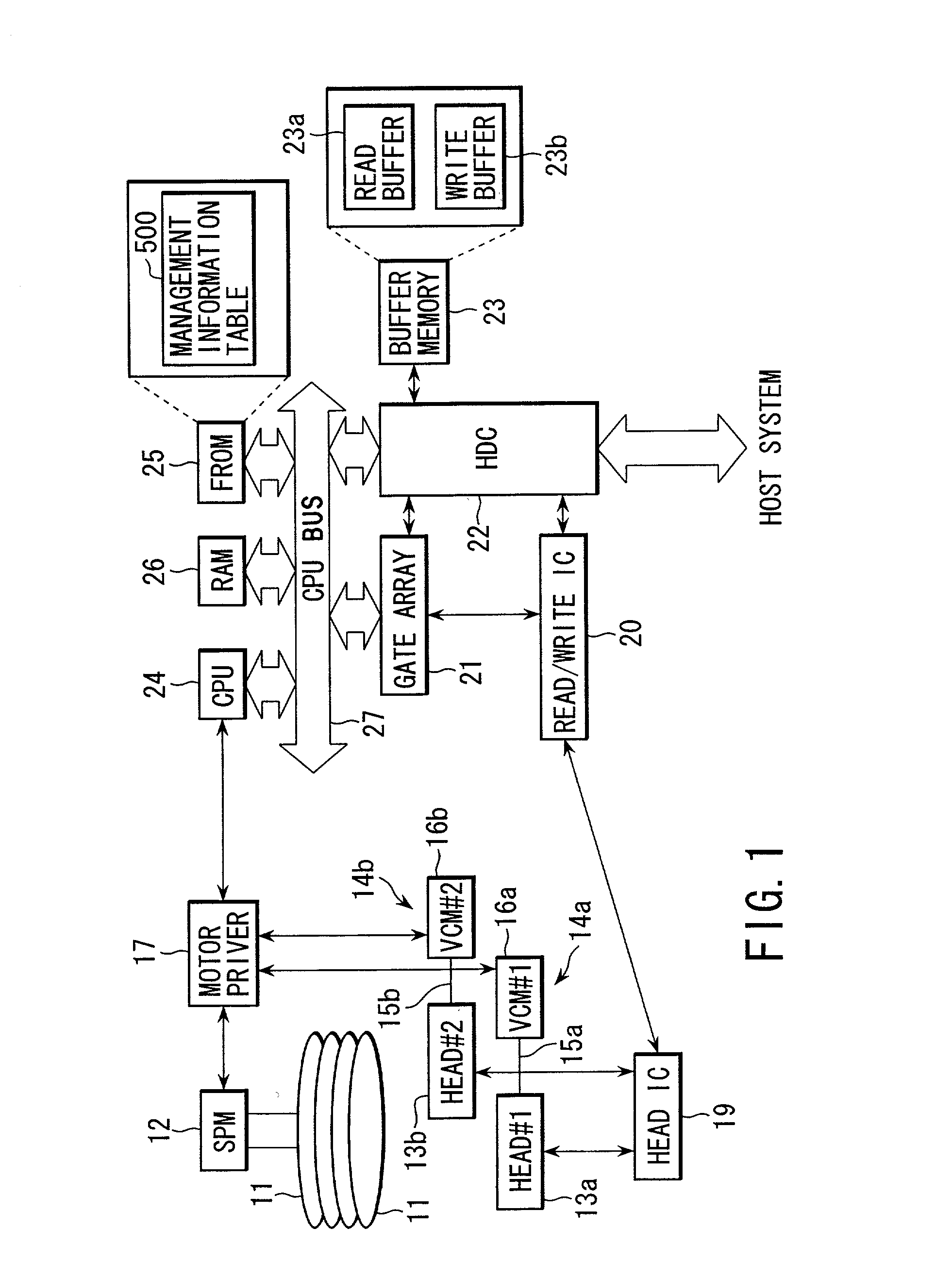
[0029] FIG. 1 is a block diagram illustrating the configuration of a hard disk drive according to a first embodiment of the invention. The hard disk drive (HDD) shown in FIG. 1 comprises a plurality of magnetic disks (magnetic disk medium) 11. Each disk 11 is supported by a spindle motor (SPM) 12 and rotated by it at high speed. Each disk 11 has two disk surfaces--upper and lower surfaces. At least one surface of each disk 11 (in this embodiment, both the disk surfaces) serves as a recording surface for recording data. Two heads, 13a (HEAD#1) and 13b (HEAD#2), are provided for each recording surface of each disk 11. To aid clarity, FIG. 1 only shows that the heads 13a and 13b are provided for one recording surface of one disk 11. The heads 13a and 13b are used to write and read data to and from each disk 11. Although in the case of FIG. 1, an HDD with a plurality of stacked disks 11 is assumed to be employed, an HDD with a single disk 11 may be employed.

[003...

second embodiment

[0064] [Second Embodiment]

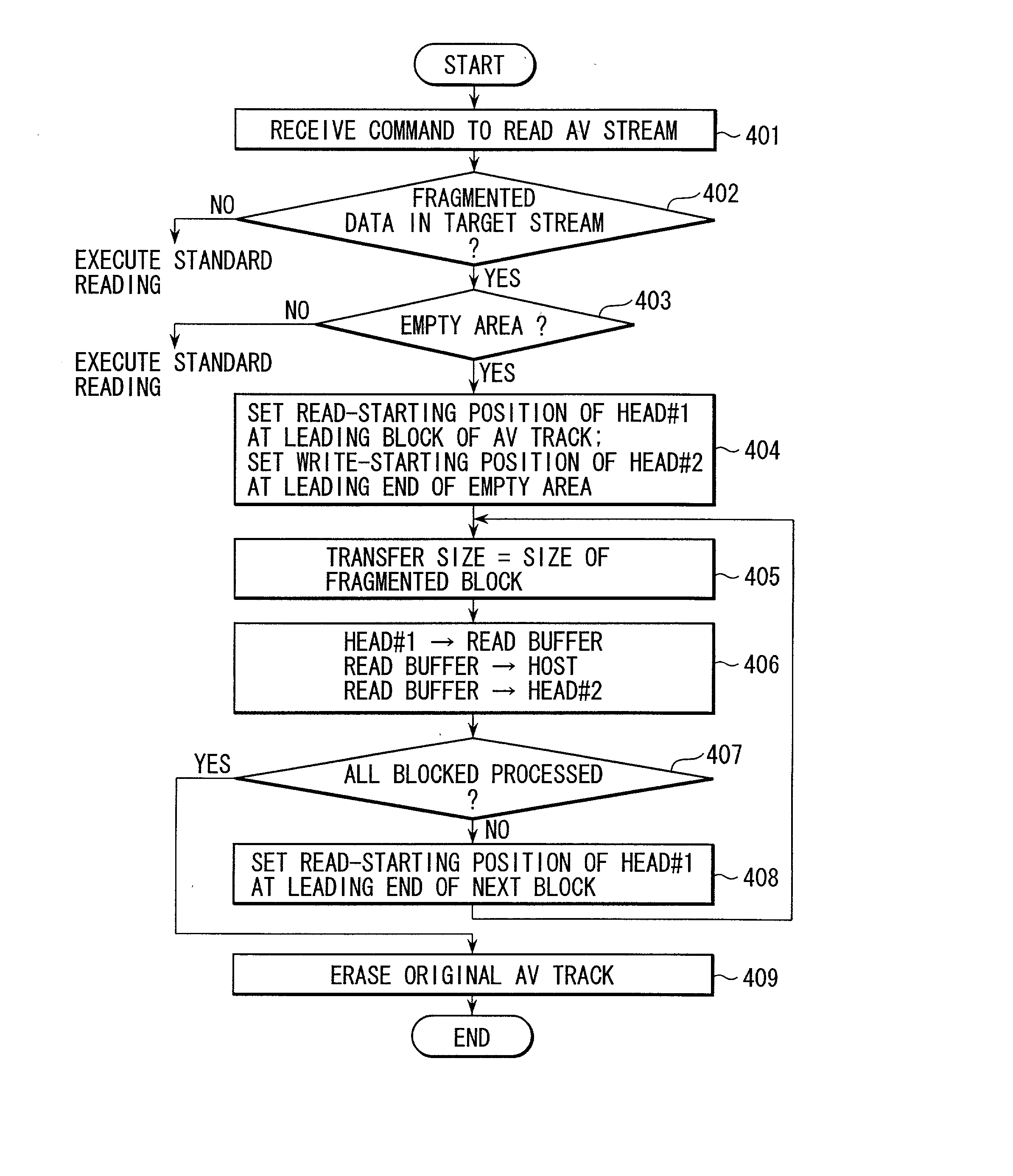
[0065] In the first embodiment, in order to execute defragmentation on a fragmented AV track in parallel with the reproduction of an AV stream corresponding to the AV track, it is necessary to secure a contiguous empty area large enough to store the AV stream. A description will now be given of a second embodiment, in which defragmentation can be executed in parallel with the reproduction of an AV stream even if there is no such empty area. A hard disk drive (HDD) employed in the second embodiment has a hardware configuration similar to that of FIG. 1. Therefore, the configuration of FIG. 1 is utilized for the sake of convenience.

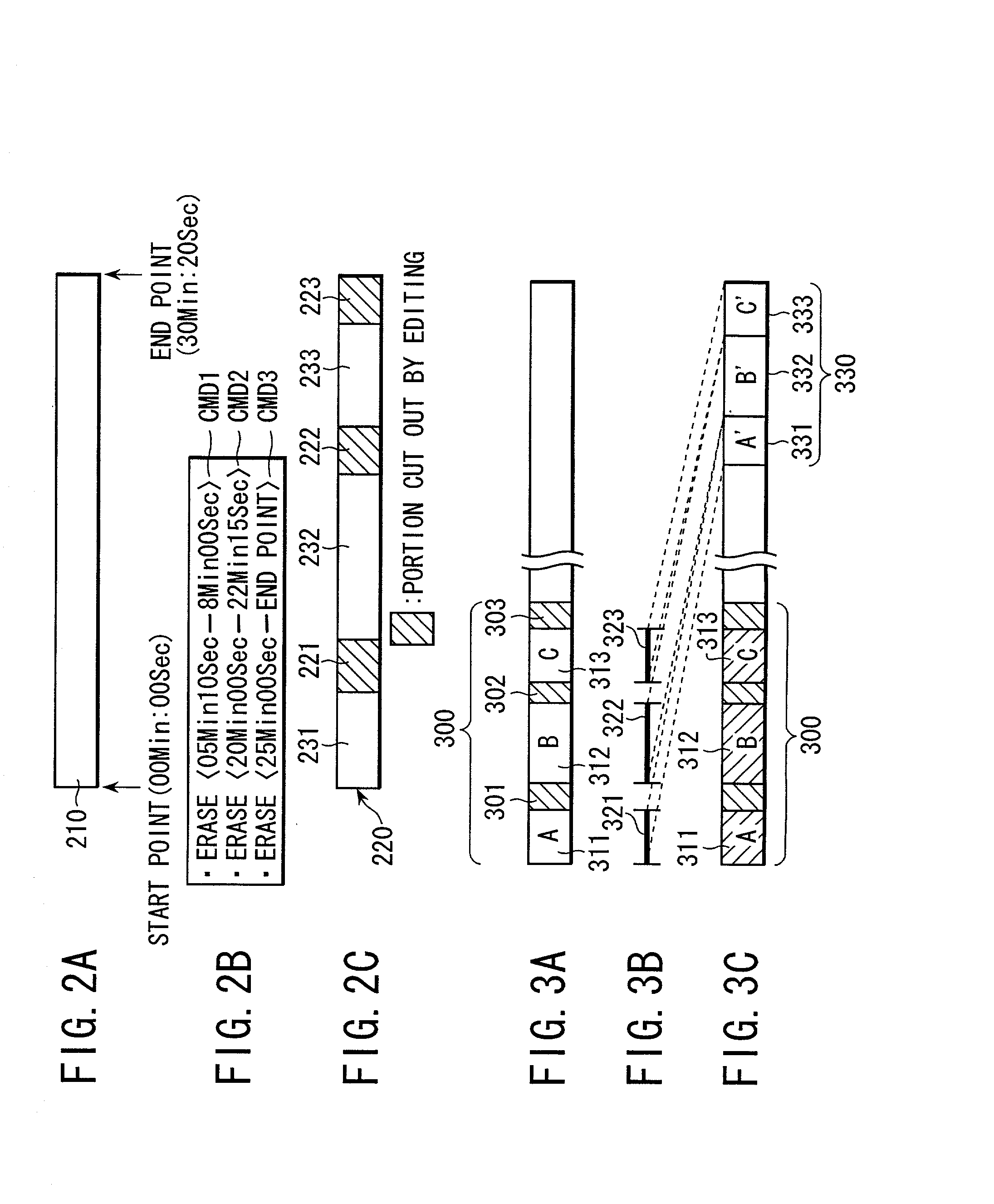
[0066] Referring first to FIGS. 6A-6C, the outline of a defragmentation process executed when reproducing an AV stream from a fragmented AV track will be described. A pre-defragmentation AV track 600 shown in FIG. 6A corresponds to an edited AV track 220 shown in FIG. 2C. In the AV track 600, data blocks 601-603 are erased as a res...

third embodiment

[0079] [Third Embodiment]

[0080] The first and second embodiments require independently-operable two heads for each recording surface of each disk, to execute a defragmentation process and the reproduction of an AV stream in a parallel manner. On the other hand, in a third embodiment of the invention, a defragmentation process and the reproduction of an AV stream can be executed in a parallel manner, even if only one head is provided for each recording surface as in the prior art. The third embodiment will be described with reference to FIGS. 8A to 8D and 9. A hard disk drive (HDD) employed in the third embodiment has a hardware configuration similar to that of FIG. 1. Therefore, the configuration of FIG. 1 is utilized for the sake of convenience. However, suppose that the third embodiment employs only the head 13a (HEAD#1 ) for each recording surface of the disks 11.

[0081] Suppose that the physical tracks on each disk 11, which contain an AV track, are two tracks, 800(#n) as shown i...


PUM

PropertyMeasurementUnit
areaaaaaaaaaaa
timeaaaaaaaaaa
AVaaaaaaaaaa

Abstract

When a host system has requested the reading of sequential data, a CPU incorporated in an HDD determines whether the data is fragmented into a plurality of data blocks on a disk. If the sequential data is fragmented, the CPU executes the control of reading the data from the disk and transferring it to the host system. In parallel with this control, the CPU also executes the control of writing the data read from the disk, to a contiguous area on the disk.

Description

CROSS-REFERENCE TO RELATED APPLICATIONS[0001] This application is based upon and claims the benefit of priority from the prior Japanese Patent Application No. 2001-065248, filed Mar. 8, 2001, the entire contents of which are incorporated herein by reference.BACKGROUND OF THE INVENTION[0002] 1. Field of the Invention[0003] The present invention relates to a disk storage system suitable for automatic defragmentation of fragmented sequential data on a disk medium by, for example, editing.[0004] 2. Description of the Related Art[0005] The storage capacity of a disk storage system, for example, a hard disk drive (hereinafter referred to as an "HDD") is now showing a tendency to increase. In accordance with this, HDDs have come to be used as AV-HDDs for recording so-called AV (Audio Visual) data such as digital music data and digital video data, etc. Since AV data is temporally-sequenced data, it is also called an AV stream (data stream).[0006] A user can edit AV data recorded in an HDD, ...

Claims


Application Information

Patent Timeline
Patent Type & Authority Applications(United States)
IPC IPC(8): G06F12/00G06F3/06G11B19/12G11B20/10G11B20/12G11B27/02G11B27/034G11B27/036
CPCG06F3/0611G06F3/064G06F3/0676G06F2206/1004G11B19/125G11B20/10G11B20/1217G11B27/034G11B27/036G11B2020/10537G11B2020/1062G11B2220/20G11B2220/2516Y10S707/99953Y10S707/99956
Inventor ARAKAWA, YUTAKAMIZUKOSHI, SEIJI
Owner KK TOSHIBA
Why Eureka
Try Eureka