Digital data system with link level message flow control

a technology of data flow control and data system, applied in data switching networks, instruments, frequency-division multiplexes, etc., can solve the problems of divergent requirements, burden on developers, and reducing the board space and ultimately the floor space that the components requir

Inactive Publication Date: 2006-04-18
MERCURY SISTEMS INC +1
View PDF10 Cites 44 Cited by
  • Summary
  • Abstract
  • Description
  • Claims
  • Application Information

AI Technical Summary

Benefits of technology

[0021]Embedded control symbols of the type discussed above may effect various flow control actions. One embedded control symbol may be sent to a transmitting node to direct it to slow or effectively suspend (e.g., to idle) its transmission rate. Another may effect canceling of a packet transmission that is in process. Yet another may cause a sender to retransmit a packet or portion thereof. In systems according to the invention, these and other flow control symbols are implemented at the link level, i.e., they originate and are implemented by adjacent nodes without involving higher logical layers of the system.
[0022]In accordance with another aspect of the present invention, a node in a link fabric interconnect as described above may pass an IDLE state control symbol over a link to an adjacent node, for example, to keep a communication pathway open as a transmitter assembles data for transmission. At the other end of a link, a receiving node can inspect and process the IDLE state control symbol without burdening its own message handling buffers.

Problems solved by technology

The current development of computer and embedded systems is burdened by divergent requirements.
Developers are burdened with the challenge of increasing device density, or functional density, while decreasing the board space and ultimately the floor space that the components require.
However, as device bandwidth demands increase, each consumes a greater portion of the total bus bandwidth, so that the addition of a small number of high-speed devices quickly offsets overall bus bandwidth gains.
Furthermore, interfacing such high bandwidth devices poses additional hardware problems in the physical environment of a typical computer system.
Continuing to work with a bus in this manner introduces several design issues.
Increasing bus width, for example, raises conflicts with physical limitations on the maximum achievable frequency, in part, because of the difficulty of maintaining skew tolerance between signals.
More signals also requires more complex hardware, e.g. pins and interface logic, resulting in higher product costs and fewer supported interfaces per device.
However, a message-passing system requires adherence to strict protocols for its operation, and is still subject to bandwidth limitations and varying traffic along its constituent links.
Moreover, the passing of messages along different links raises many potential failure points, where message corruption or deadlock may occur.
Further, the prior art use of side band signal pins to support handshake signaling comes at a cost: more pins, more logic and more board “real estate.” The alternative use of explicit control message packets for this purpose can prove expensive from a bandwidth and latency point of view.

Method used


Image

  • Digital data system with link level message flow control
  • Digital data system with link level message flow control
  • Digital data system with link level message flow control

Examples


Embodiment Construction

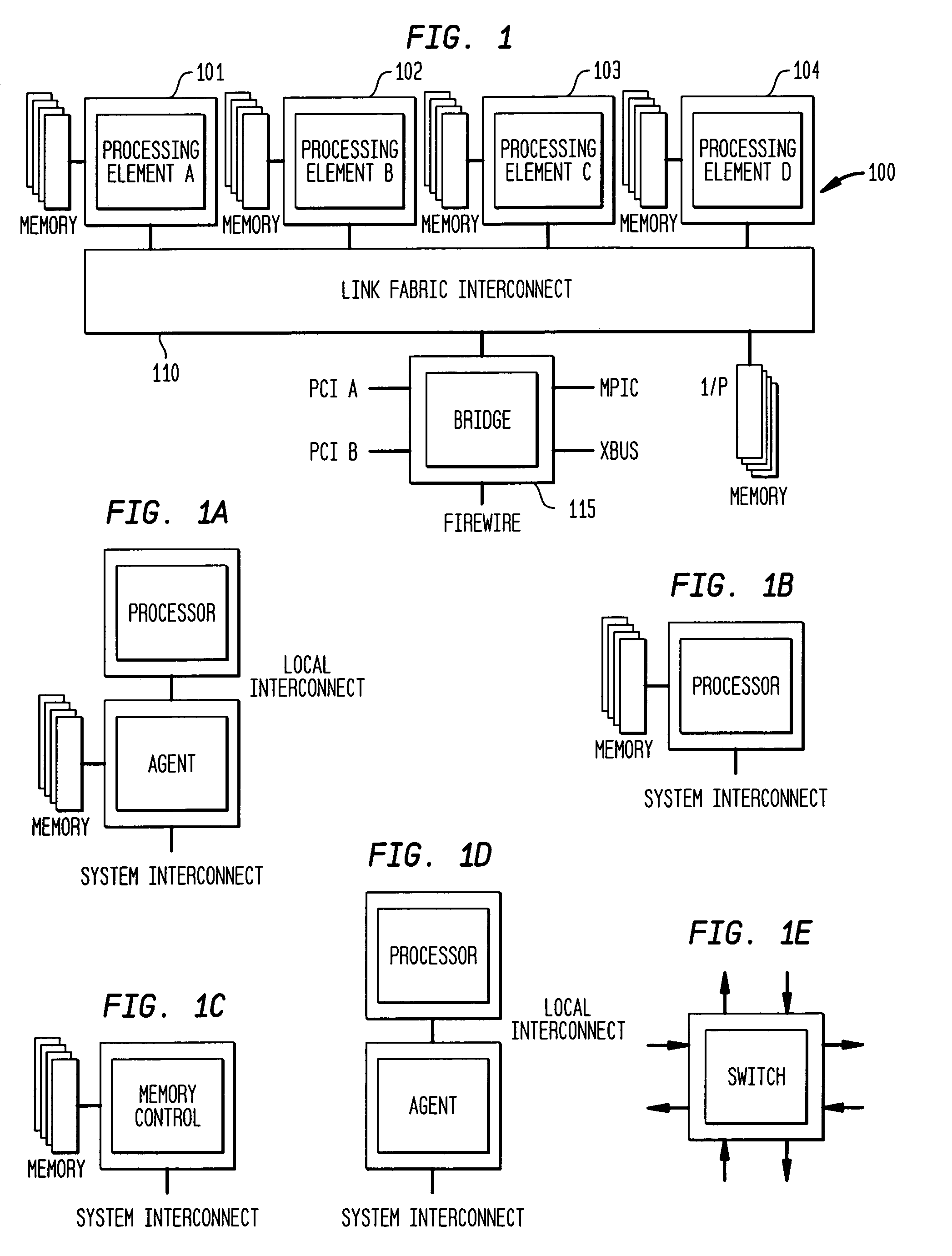
[0038]FIG. 1 illustrates generally an embodiment of a digital data system 100 employing link interconnect message communication in accordance with the present invention. The system includes a plurality of nodes, some of which are shown as digital devices 101, 102, 103, 104, . . . . In the illustrated embodiment, these are processors with associated memories, though, they may also comprise other digital devices capable of generating, handling and / or passing message packets.

[0039]In this regard, it will be understood that messaging over interconnected links as described herein has wide application, e.g., to systems that implement direct memory access, to systems that provide communications between processors in a domain, as well as to systems that provide such communications between lower-level digital devices or components. Examples of the former are provided by FIGS. 1 and 1A. Examples of the latter are provided by FIGS. 1B and 1D (a stand-alone processor or processor / agent with no ...


PUM


Abstract

A digital data system comprises a plurality of links for passing messages between nodes, which may be end points such as memory or processing units, or intermediate or branch points such as routers or other devices in the system. A link level flow control is implemented by control symbols passed between adjacent nodes on a link to efficiently regulate message burden on the link. The control symbols may be embedded within in a message packet to quickly effect control on a link—such as reducing data flow, requesting retransmission of corrupted data, or other intervention—without disruption of the ongoing packet reception. A control symbol may be recognized within the packet by a flag bit, a marker such as a transition in a signal, or a combination of characteristics. The control symbol may be a short word, having a control action identifier code at defined bit positions to indicate the desired link-level control function. A node receiving the control symbol implements the designated control action while maintaining packet order data (such a bit positions and byte counts), and applying message housekeeping processing (such as error checking) as though the control symbol were absent. The control symbol is thus embedded in a manner such that a receiving node need not receive a complete message, or even a complete packet, before acting on the control symbol. The beginning and end of the interrupted packet, meanwhile, are handled as a single message packet, and are processed by the receiving node in properly-aligned bit positions, allowing message flow to continue along the link without interruption. Thus, retransmission of the affected packet or message is not required. The result is that control operations dictated by the embedded control symbol are effected immediately and without slowing down communications.

Description

REFERENCE TO RELATED APPLICATIONS[0001]This application claims the benefit of priority of U.S. Provisional Patent Application Ser. No. 60 / 175,856, filed Jan. 13, 2000, entitled “Rio Bus Protocol,” the entirety of the teachings of which are incorporated by reference.BACKGROUND OF THE INVENTION[0002]The current development of computer and embedded systems is burdened by divergent requirements. On one hand performance is expected to increase exponentially, while on the other hand the price of components is driven by market factors to continuously decrease. Developers are burdened with the challenge of increasing device density, or functional density, while decreasing the board space and ultimately the floor space that the components require. The physics of signal handling and transmission, and the need for standardized interconnects and scalable systems, impose further bounds on system development.[0003]Many existing computer systems are built around a single high-speed common bus. Whe...

Claims


Application Information

Patent Timeline
Patent Type & Authority Patents(United States)
IPC IPC(8): G01R31/08H04L12/26
CPCH04L47/35H04L47/10H04L47/431
Inventor FRISCH, ROBERT C.MARIETTA, BRYAN D.BOUVIER, DANIEL L.
Owner MERCURY SISTEMS INC
Why Eureka
Try Eureka