Trenching machine

a technology of a turning machine and a turning shaft, which is applied in the direction of hand-operated machines/dredgers, soil shifting machines/dredgers, constructions, etc., can solve the problems of difficulty in removing the digging implement the manoeuvrability of existing trenching machines is generally less than desirable, and the turning of the turning shaft is typically relatively shallow

Inactive Publication Date: 2002-09-26
DICKINS MCLEOD DEV
View PDF6 Cites 7 Cited by
  • Summary
  • Abstract
  • Description
  • Claims
  • Application Information

AI Technical Summary

Benefits of technology

[0027] When sufficient tension is maintained in the belts and the second motor means is activated, the second motor means drives the drive pulleys, causing the driven pulleys to rotate in unison. Rotation of the driven pulleys, in turn, causes the drive wheels to rotate in unison to move the machine. When it is desired to change the machine direction, the belts are loosened to the point where the driven pulleys are able to rotate independently of the drive pulleys and therefore also independently of one another. This enables the drive wheels to be rotated independently of one another, thereby enabling the user to manoeuvre the machine as desired.

Problems solved by technology

Such trenches are typically relatively shallow.
Difficulties exist in removing the digging implement of existing trenching machines, which are generally in the form of chain-mounted digging teeth.
Moreover, the manoeuvrability of existing trenching machines has generally been found to be less than desirable, particularly when used for applications requiring relatively tight cornering of the machine.
Furthermore, existing machines generally undesirably experience a temporary reduction in power delivered to the digging implement when raising and lowering the chain guide carrying the digging implement.

Method used


Image

  • Trenching machine
  • Trenching machine
  • Trenching machine

Examples


Embodiment Construction

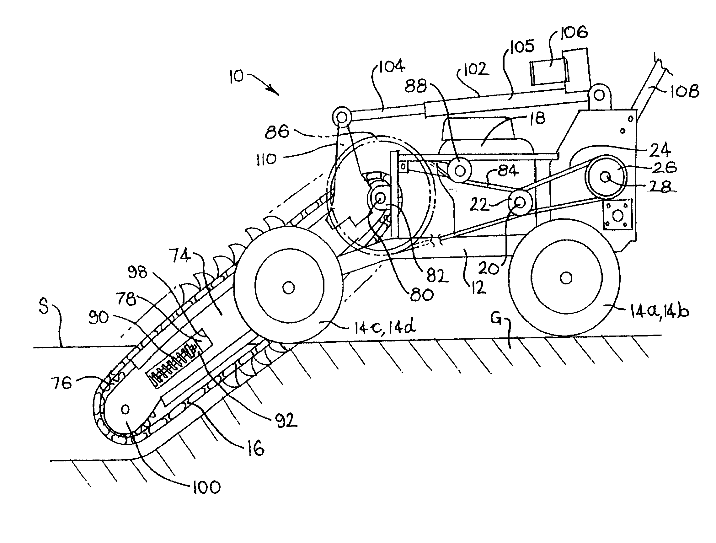
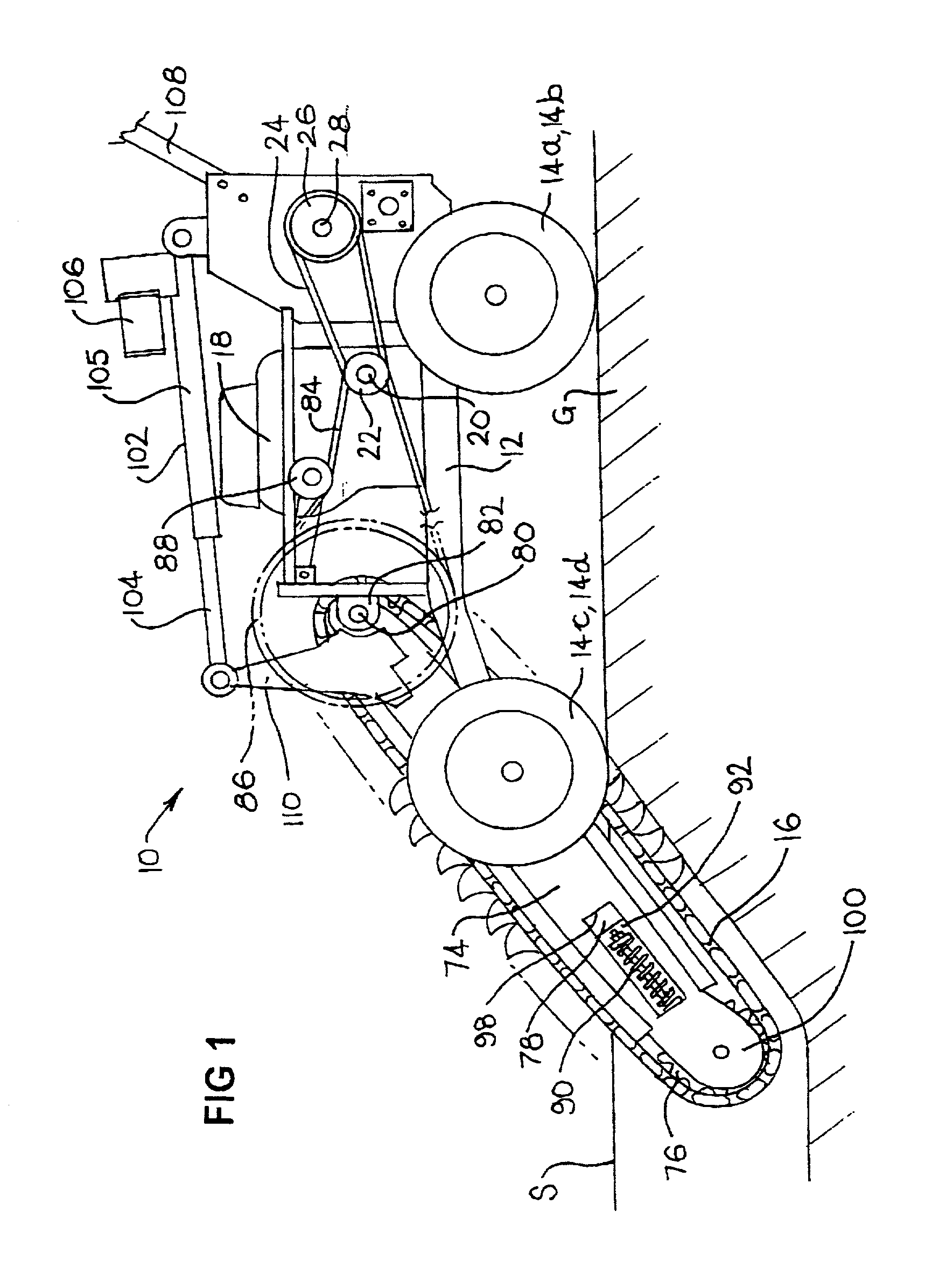
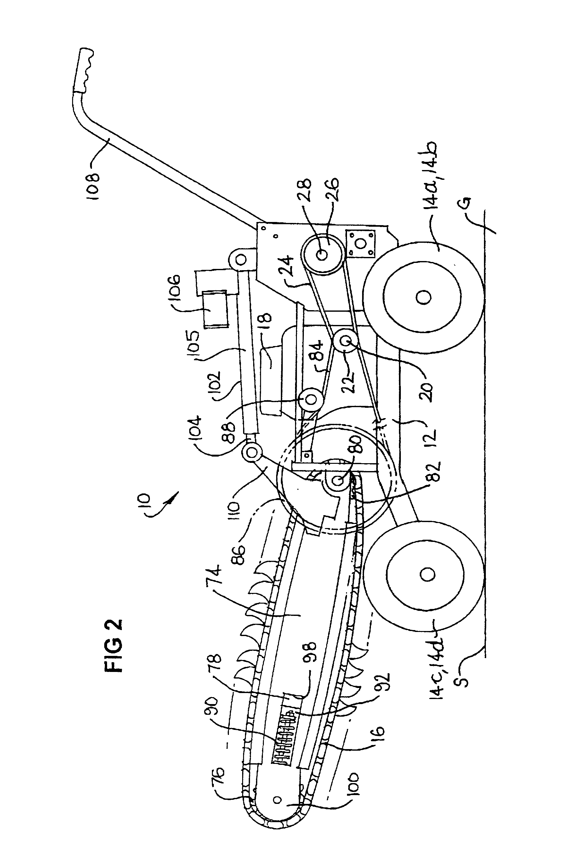
[0078] A trenching machine 10 is illustrated in the drawings. The trenching machine 10 includes a frame 12, which includes wheels 14a, b, c, d. In the embodiment illustrated, a first motor means for driving a digging chain 16, and a second motor means for driving at least one of the wheels 14a, b, c, d, are integrated into the form of a petrol engine 18. The engine 18 is mounted on the frame 12.

[0079] The engine 18 includes an output shaft 20. An output pulley 22 is mounted on one end of the output shaft 20. A belt 24 extends around the output pulley 22 and around a gearbox input pulley 26. The pulley 26 is mounted on one end of a gearbox input shaft 28 of a gearbox 30.

[0080] The gearbox 30 includes a lubricating oil inlet port 31 and bearing assemblies 34 and 36. The internal workings of the gearbox 30 are not further described.

[0081] Gearbox output pulleys 32, 33 are connected to one end of a gearbox output shaft 34. It is to be appreciated that rotation of the gearbox input pulle...


PUM


Abstract

A trenching machine (10) comprising a wheeled frame (12) and a first motor means (18) mounted on the frame (12). The first motor means (18) drives a digging chain (16) carried on a chain guide (74) extending from the machine (10). The chain guide (74) is pivotally mounted coaxially with a drive chain drive sprocket (82). A means (102) for pivotally moving the chain guide (74) relative to the frame (12). a locking means (102, 104, 105) to lock the chain guide (74) in a desired pivotal position, and a second motor means (18) mounted on the frame (12), are also provided. The second motor means (18) drives at least one of the machine wheels (14a, b) for moving the machine (10) along the ground (G) The second motor means (18) is releasably engaged to the at least one of the machine wheels (14a, b).

Description

[0001] The present invention relates to trenching machines and, more particularly, to hand-operated trenching machines. It is to be appreciated, however, that the invention is not limited thereto.[0002] 1. Background of the Invention[0003] Trenching machines of the form addressed by the present invention are designed primarily for digging trenches in the ground. Applications for such trenches include the installation of pipes, drains, cables, and the like. Such trenches are typically relatively shallow.[0004] Difficulties exist in removing the digging implement of existing trenching machines, which are generally in the form of chain-mounted digging teeth.[0005] Moreover, the manoeuvrability of existing trenching machines has generally been found to be less than desirable, particularly when used for applications requiring relatively tight cornering of the machine.[0006] Furthermore, existing machines generally undesirably experience a temporary reduction in power delivered to the dig...

Claims


Application Information

Patent Timeline
Patent Type & Authority Applications(United States)
IPC IPC(8): E02F5/06E02F5/10
CPCE02F5/06
Inventor DICKINS, HARVEY PHILIP
Owner DICKINS MCLEOD DEV
Why Eureka
Try Eureka