
Apparatus and Method for Interference Suppression Transmission

Inactive Publication Date: 2002-11-14
OPTIS WIRELESS TECH LLC
View PDF7 Cites 29 Cited by
  • Summary
  • Abstract
  • Description
  • Claims
  • Application Information

AI Technical Summary

Benefits of technology

[0012] The object of the present invention is to provide a piece of apparatus for interference suppression transmission by which a communication end may obtain with a simple configuration signals without effect of interference or delay waves.

Problems solved by technology

However, pieces of communication apparatus provided with a conventional interference canceller have had the following problems.
That is, the above interference canceller requires a large amount of calculations, and information (for example, unique words) on all the users using the same frequency.
Therefore, there has been a problem that it is difficult to install a piece of communication apparatus provided with the above conventional interference canceller in pieces of mobile station apparatus, considering the electric power consumption, the cost, the size, the complexity of the control signals, and so on.
Moreover, pieces of communication apparatus provided with the conventional interference canceller have had a problem that the quality of received signals is deteriorated by the effects of delay waves, when there are the above delay waves in channels used, as the above pieces of communication apparatus suppress only the effect of interference.

Method used


Image

  • Apparatus and Method for Interference Suppression Transmission
  • Apparatus and Method for Interference Suppression Transmission
  • Apparatus and Method for Interference Suppression Transmission

Examples


embodiment 1

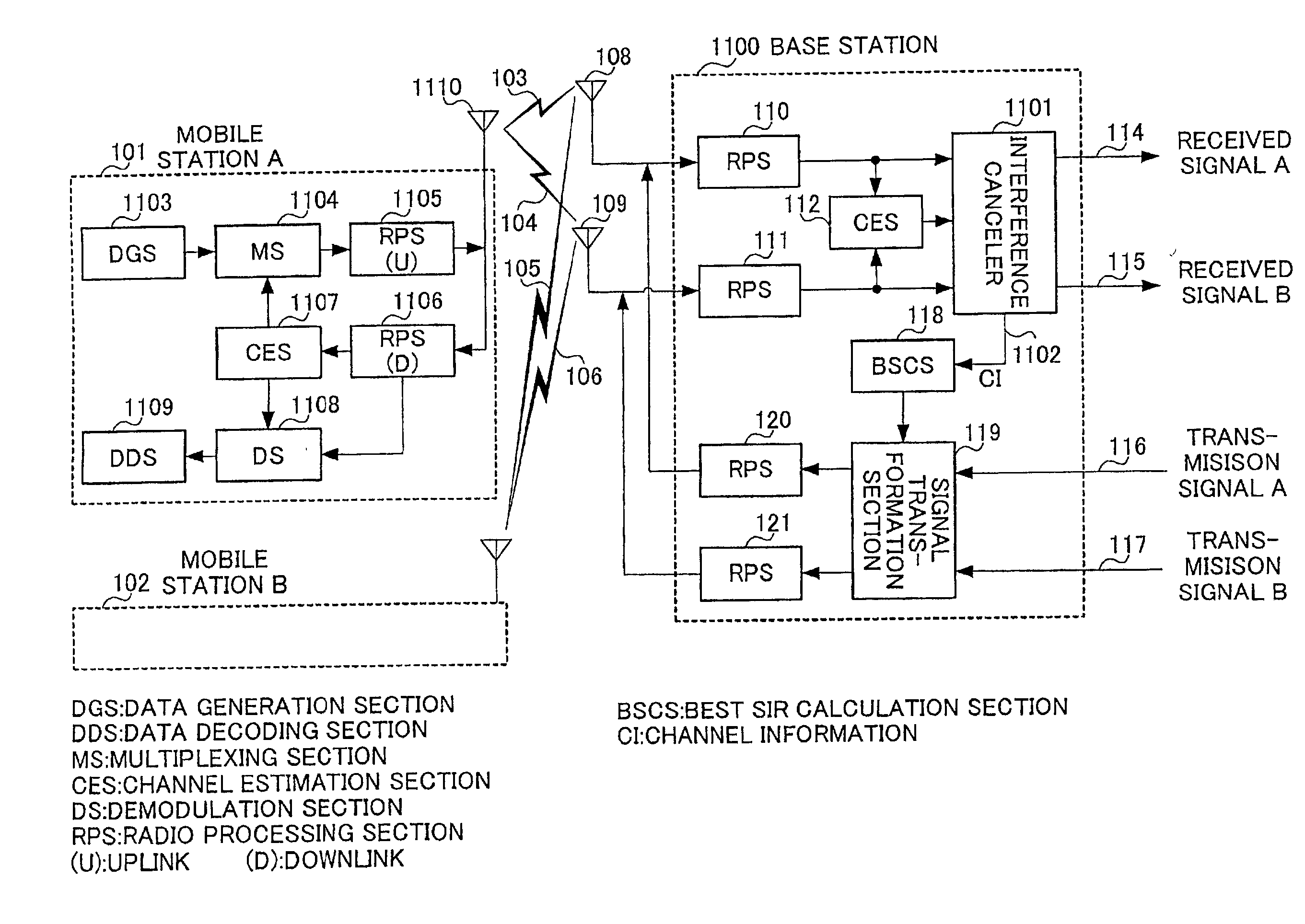
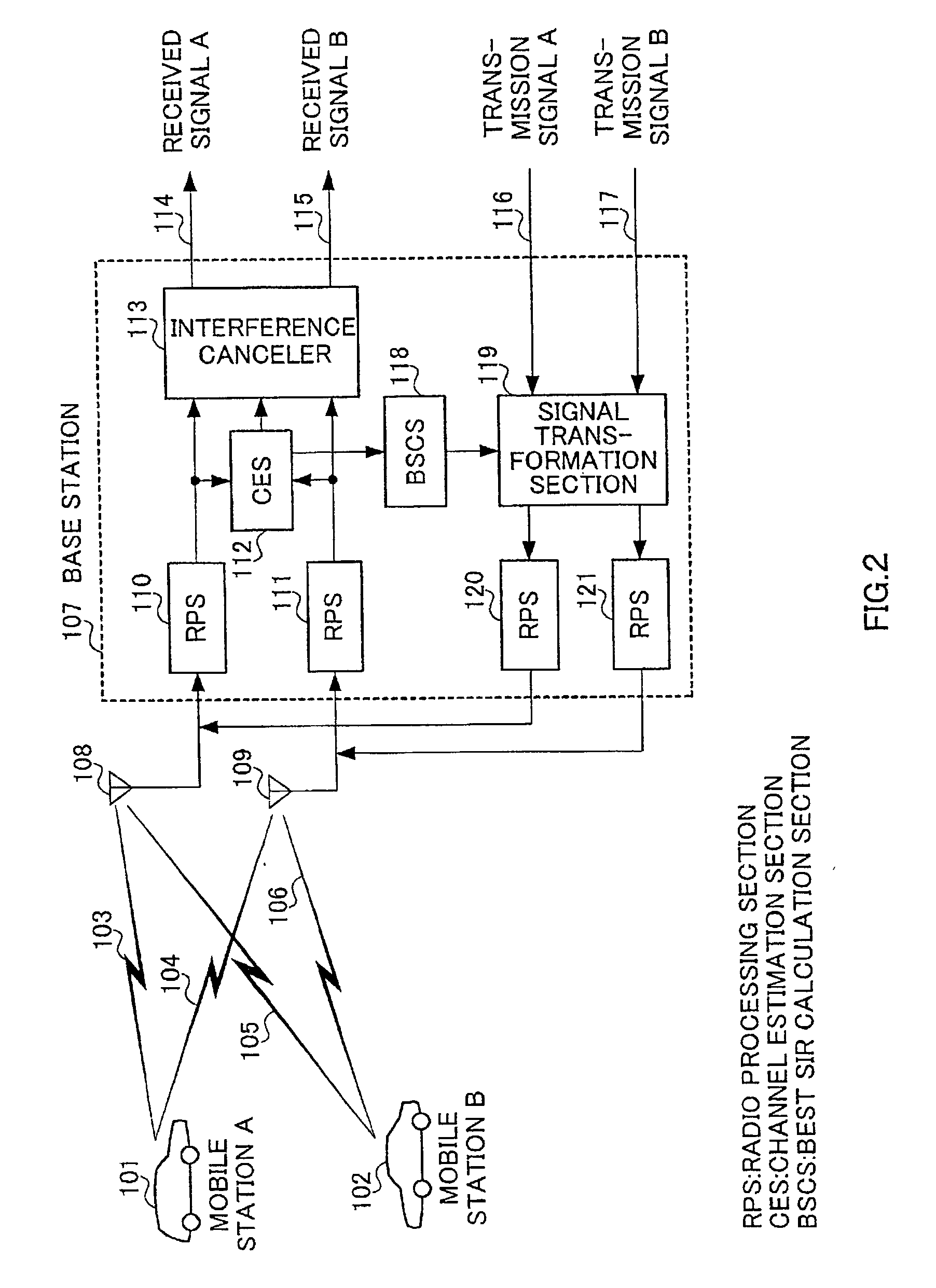
[0031] FIG. 2 is a view showing a configuration of a piece of base station apparatus provided with a piece of apparatus for interference suppression transmission according to the present invention, and a system in which the above base station apparatus performs radio communication with pieces of mobile station apparatus. FIG. 2 shows that a piece of base station apparatus 107 provided with a piece of apparatus for interference suppression transmission according to the present embodiment performs radio communication with a piece of mobile station apparatus (A) 101 and that of (B) 102 according to a TDD (Time Division Duplex) method.

[0032] Here, the mobile station apparatus (A) 101, and that of (B) 102 use wireless channels 103, 104 and those 105, 106, respectively, for communication with the base station apparatus 107. All the above wireless channels use the same frequency. And the present embodiment will be described for one example where there are two pieces of mobile station appar...

embodiment 2

[0051] The embodiment 2 will be described for a case where more stable operation of the whole system is realized in the embodiment 1. In the above embodiment 1, the best SIR calculation section 118 calculates an inverse matrix, using channel states estimated in the channel estimation section 112. However, there is a condition that there is no inverse matrix, and, moreover, the above system becomes unstable as a transmission system, as the order of the solution becomes large when an inverse matrix which is calculated under a situation close to the above condition is used.

[0052] Then, in the present embodiment, it is configured in the above case that transmission to a piece of mobile station apparatus using channels with a possibility for instability is interrupted, and an inverse matrix is obtained again, using only states of stable channels. That is, as it is impossible to realize transmission with sufficient quality as the whole system even in the case of transmission with forced u...

embodiment 3

[0057] The embodiment 3 will be described for a case where the coefficients used in the signal transformation section 119 in the embodiment 1 or 2 are obtained by training.

[0058] Hereinafter, a piece of apparatus for interference suppression transmission according to the present embodiment will be described referring to FIG. 4. Here, the following description will be performed referring to the above embodiment 2.

[0059] FIG. 4 is a view showing a configuration of a piece of base station apparatus provided with a piece of apparatus for interference suppression transmission according to the embodiment 3 of the present invention, and a system in which the above base station apparatus performs radio communication with pieces of mobile station apparatus. Here, components which are shown in FIG. 4 and are similar to those in the embodiment 2 (FIG. 3) {{{Translator's comment: the original "(FIG. 4)" could be corrected to "(FIG. 3)"}}} are denoted by the same reference numerals as those in F...


PUM


Abstract

A channel estimation section 112 estimates the states of channels used for pieces of mobile station apparatus (A) and (B), using signals demodulated by radio processing sections 110, 111. A best SIR calculation section 118 calculates coefficients to be used for signal transformation by inverse matrix calculation, using the above channel estimation values by the above channel estimation section 112. A signal transformation section 119 performs linear transformation of transmission signals to the above pieces of mobile station apparatus, using the above coefficients from the above best SIR calculation section 118. Radio processing sections 120, 121 modulates each transmission signal after the above linear transformation for transmission through antennas 108, 109, respectively.

Description

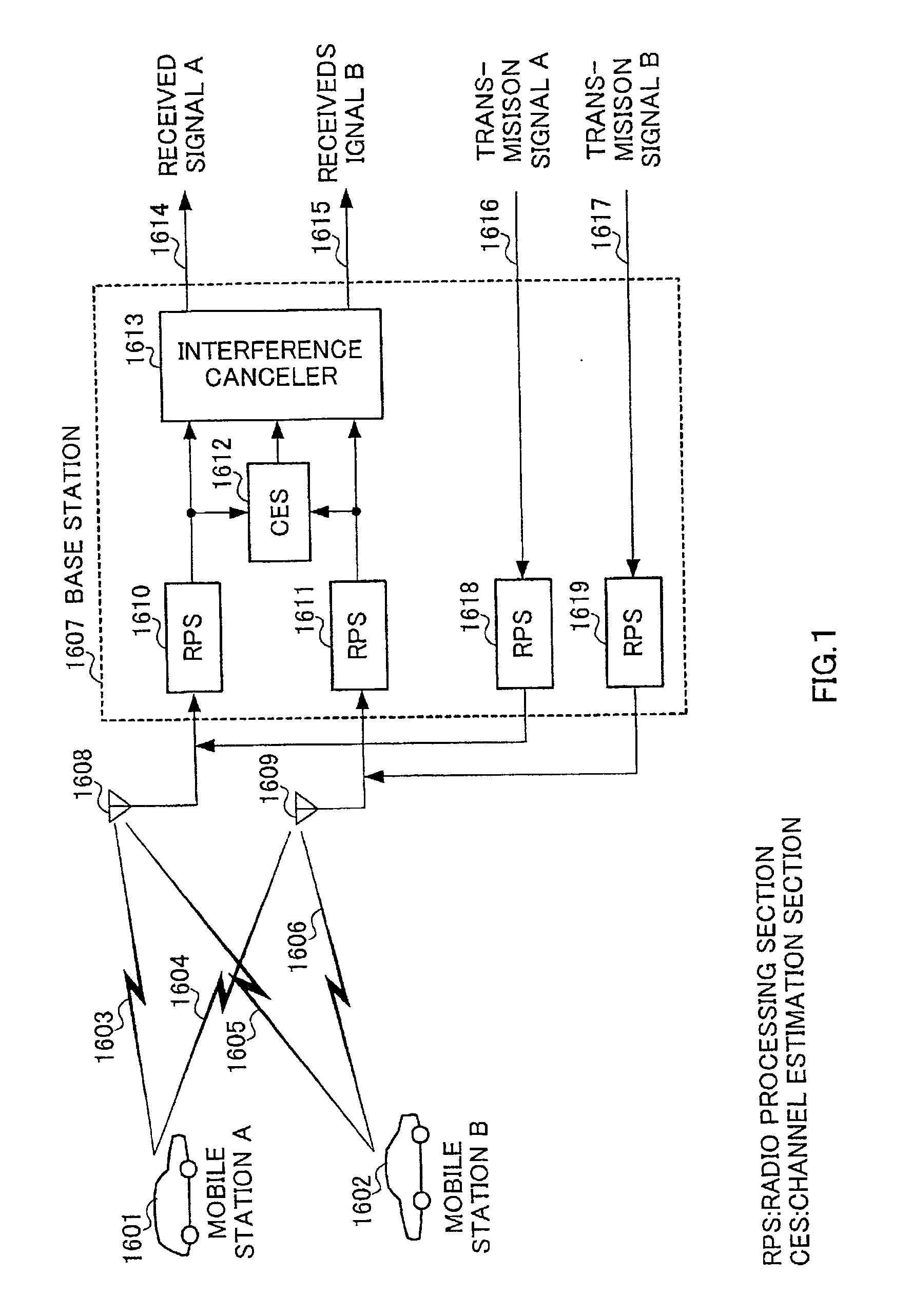
[0001] The present invention relates to a piece of communication apparatus in a mobile communication system, and, especially, to a piece of communication apparatus provided with an interference canceller.[0002] Conventional communication systems in which a piece of communication apparatus provided with an interference canceller is used are shown as follows. FIG. 1 is a view showing a configuration of a piece of conventional base station apparatus provided with an interference canceller, and a system in which the above base station apparatus performs radio communication with pieces of mobile station apparatus.[0003] FIG. 1 shows that a piece of mobile station apparatus (A) 1601 and that of (B) 1602 perform radio communication with a piece of base station apparatus 1607. Here, the mobile station apparatus (A) 1601, and that of (B) 1602 use wireless channels 1603, 1604 and those 1605, 1606, respectively, for communication with the base station apparatus 1607. All the above wireless cha...

Claims


Application Information

Patent Timeline
IPC IPC(8): H04B1/10H04B7/06H04B7/08H04B7/26H04B15/00H04L1/06
CPCH04B7/0608H04L1/06H04B7/0854H04B7/08
Inventor UESUGI, MITSURU
Owner OPTIS WIRELESS TECH LLC
Learn More