Filling apparatus and filling method therefor

a filling apparatus and pressurized technology, applied in the direction of liquid handling, packaging goods, transportation and packaging, etc., can solve the problems of inaccurate amount of filling liquid to be filled into the container, inefficient exhaust, and increasing the time required for the filling operation

Inactive Publication Date: 2002-12-05
SHIBUYA IND CO LTD
View PDF30 Cites 24 Cited by
  • Summary
  • Abstract
  • Description
  • Claims
  • Application Information

AI Technical Summary

Problems solved by technology

If the above described pressurized filling apparatus is used for an unpressurized filling operation, the following problems may occur: First, in the unpressurized filling operation, a filling liquid may be heated and sterilized, so that it may be filled into a container while hot.
However, hot steam from the hot filling apparatus may flow into the gas passage and may be cooled and condensed there, so that the diameter of the passage may be reduced to make the exhaust inefficient, thereby increasing the time required for ...

Method used


Image

  • Filling apparatus and filling method therefor
  • Filling apparatus and filling method therefor
  • Filling apparatus and filling method therefor

Examples


Embodiment Construction

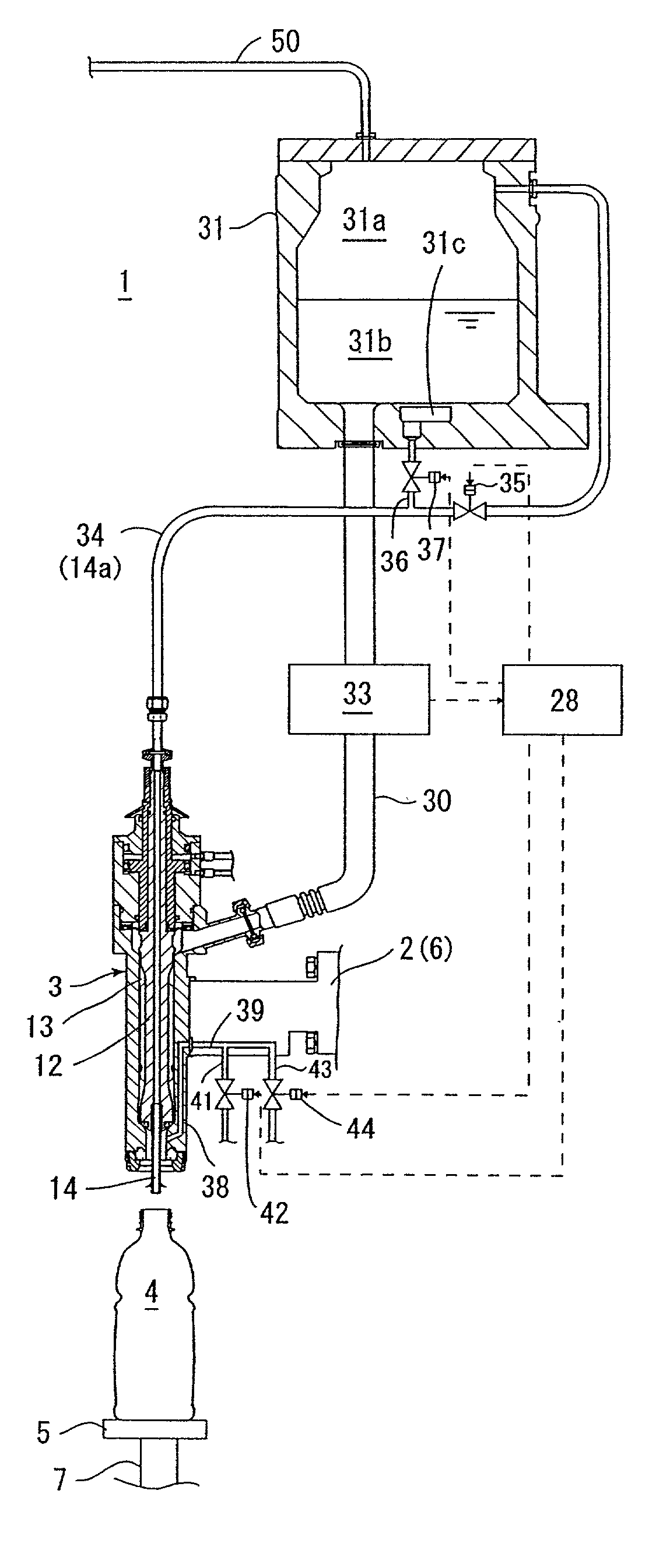
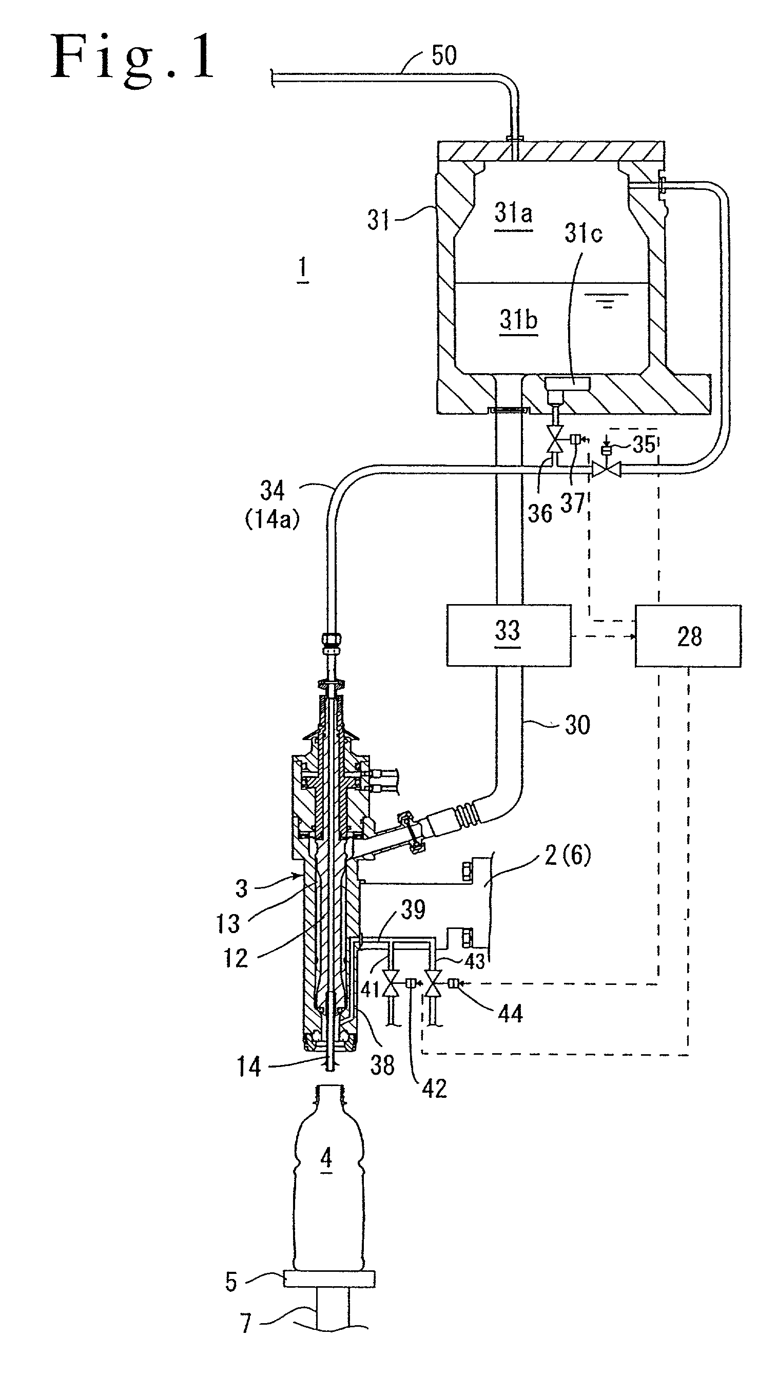
[0021] The present invention will be described in connection with the illustrated embodiments. In FIG. 1, reference numeral 1 denotes a rotary filling apparatus to which the present invention has been applied. The rotary filling apparatus 1 comprises a rotating member 2 (partially illustrated) rotated by drive means (not shown), ring-shaped storage tanks 31 provided above the rotating member 2 to store filling liquid therein, filling valves 3 provided below the respective storage tanks 31 at respective circumferential positions equally spaced from the corresponding storage tanks 31, in order to carry out filling of liquid, and a table 5 provided below the filling valve 3 and on which a container 4 is placed.

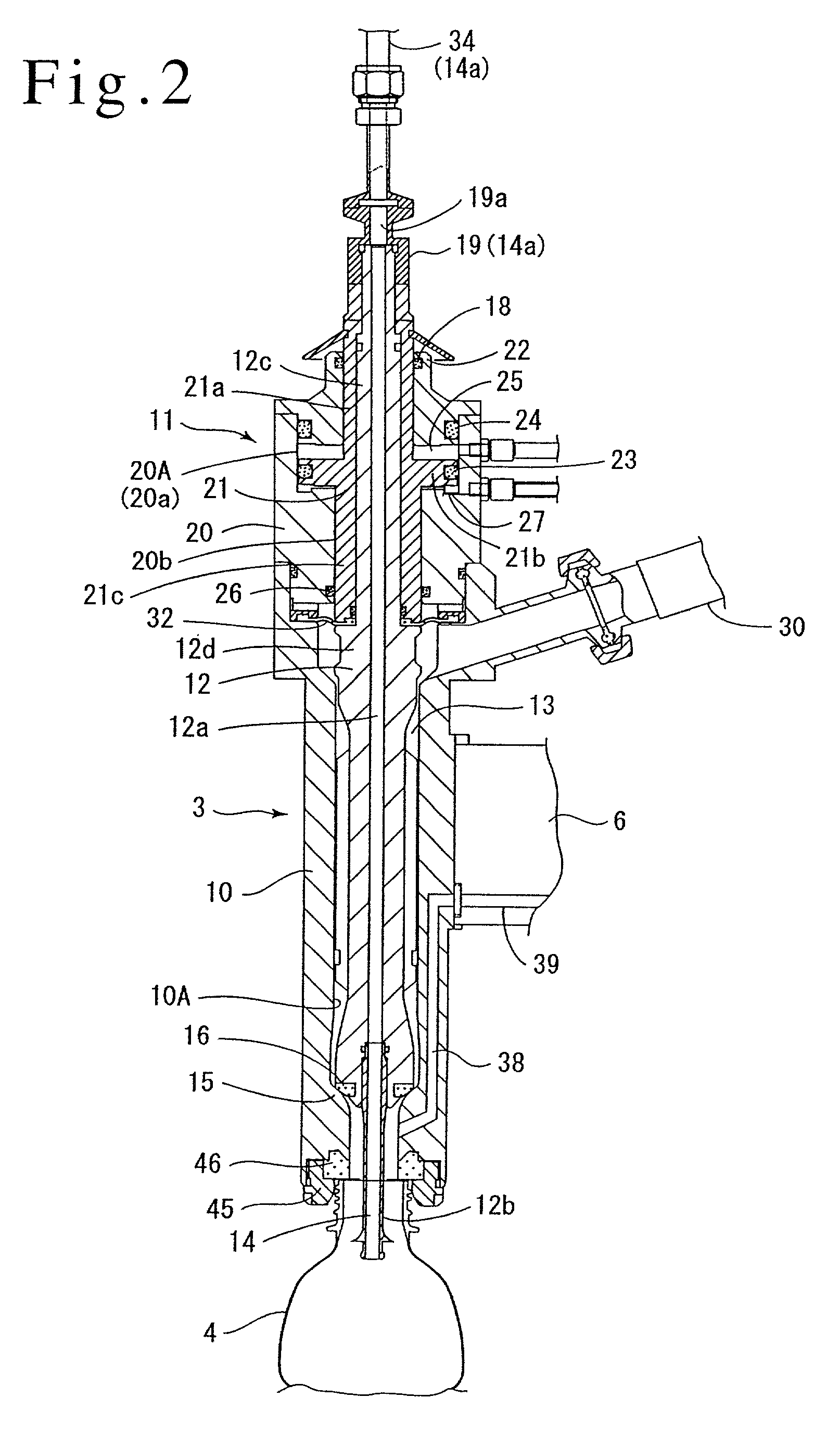
[0022] The storage tank 31 stores filling liquid 31b with a gas space 31a. Further, the filling valves 3 are each attached to an upper plate 6 of the rotating member 2 so as to extend downward, whereas the table 5 is attached to a piston rod 7 (only the piston rod is illustrated)...


PUM

PropertyMeasurementUnit
Pressureaaaaaaaaaa

Abstract

A filling apparatus 1 comprises a gas passage 14 connected to a storage tank 31 via a connection passage 14a, a first gas valve 35 that opens and closes the gas passage, a pressure gas passage 41 connected to a pressure gas supply source, a pressure gas valve 42 that opens and closes the pressure gas passage, an exhaust passage 43 that allows an interior of a container 4 to communicate with an exterior thereof, and an exhaust valve 44 that opens and closes the exhaust passage. With this filling apparatus, before a pressurized filling operation, both the gas passage and the pressure gas passage are opened to pressurize the interior of the container with a carbonated gas supplied through both passages. Further, also before a unpressurized filling operation, both the gas passage and the pressure gas passage are opened to perform a flushing operation in which droplets are discharged from the gas passage with air exhausted from the container into the storage tank via the gas passage. Then, after the filling operation, both the gas passage and the exhaust passage are opened to discharge a certain amount of filling liquid remaining in the gas passage, into the container.

Description

[0001] The present invention relates to a pressurized filling apparatus for filling a container with filling liquid such as a carbonated drink, and more specifically, to a filling apparatus for filling a container with filling liquid such as a non-carbonated drink that can also be used for unpressurized filling and a filling method therefor.DESCRIPTION OF THE PRIOR ART[0002] A well-known pressurized filling apparatus that fills a container with filling liquid such as a carbonated drink accommodates filling liquid in a storage tank together with a pressurized carbonated gas, supplies the carbonated gas in the storage tank to the interior of a sealed container via a gas passage formed in a filling valve and pressurizes the interior of the container, opens the filling valve to start a filling operation when the pressure in the container becomes equal to that in the storage tank, ends the filling operation once the filled amount reaches a predetermined value, and stops applying pressure...

Claims


Application Information

Patent Timeline
IPC IPC(8): B67C3/06B67C3/10
CPCB67C3/10
Inventor TSUKANO, KENICHIEDA, MASAAKIKAMORI, SHINYATANIKAWA, KATSUNORI
Owner SHIBUYA IND CO LTD
Why Eureka
Try Eureka