
Fluid collection safety syringe

a safety syringe and fluid collection technology, applied in the field of safety syringes, can solve the problems of dirty needles, high risk of infection with hiv or hepatitis, and accidental sticks with dirty needles, etc., and achieve the most dangerous times for accidental sticks, dirty needles, and exposed

Inactive Publication Date: 2002-12-05
NUSAF
View PDF0 Cites 5 Cited by
  • Summary
  • Abstract
  • Description
  • Claims
  • Application Information

AI Technical Summary

Benefits of technology

[0011] It is an object of the invention to help prevent the transmission of AIDS and other diseases through accidental sticks with contaminated needles.
[0013] It is an object of the invention to provide a safety syringe which minimizes the risk of damage to the veins of the patient.

Problems solved by technology

The risk of contracting diseases such as HIV or hepatitis from accidental sticks with dirty needles is a potentially deadly hazard for medical professionals.
One of the most dangerous times for accidental sticks is during blood collection.
At this time, the needle is dirty and exposed and an accidental stick is possible from this point on.
Also, personnel handling medical refuse may be stuck after the syringe has been discarded.
All too frequently, this is not the case.
Children may also behave uncontrollably during blood collection.
Such activity on the part of the patient obviously increases the risk of an accidental stick.
If the patient becomes agitated, his movements may cause the needle to damage the vein or the surrounding tissue.
Even if the patient is still, the movement of the syringe by the medical professional as she is changing tube may cause damage to the vein.

Method used


Image

  • Fluid collection safety syringe
  • Fluid collection safety syringe
  • Fluid collection safety syringe

Examples


Embodiment Construction

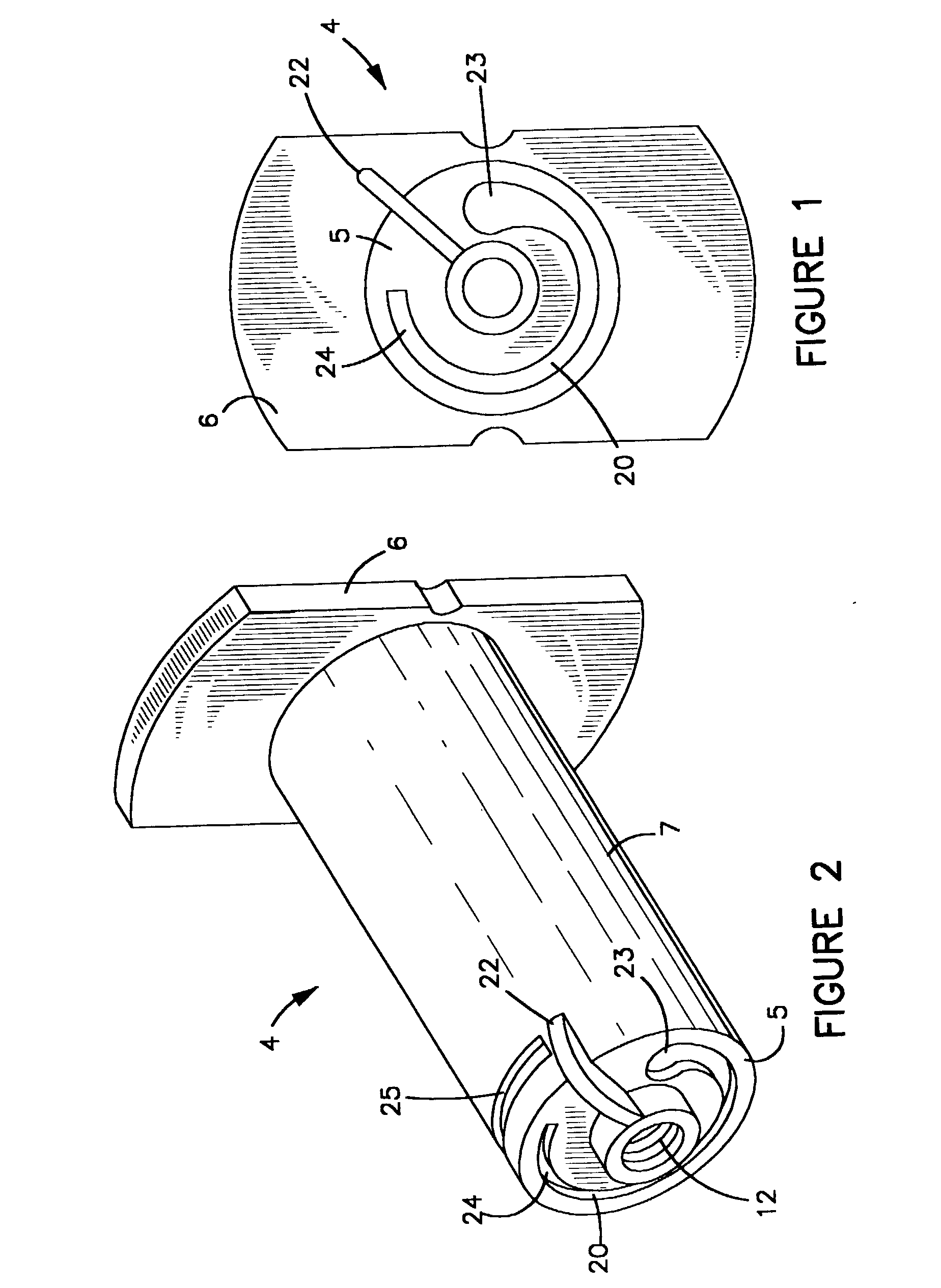
[0032] The invention is a safety syringe 1 for use with one or more vacuum specimen tubes 2, preferably sealed with a stopper 3. Syringe 1 comprises a shroud 4 having a first end 5, a second end 6, and sidewalls 7 extending therebetween. First end 5, second end 6, and sidewall s 7 define a shroud chamber 8. Second end 6 is preferably open in order to provide access to shroud chamber 8. Shroud chamber 8 is sized to receive vacuum specimen tube 2.

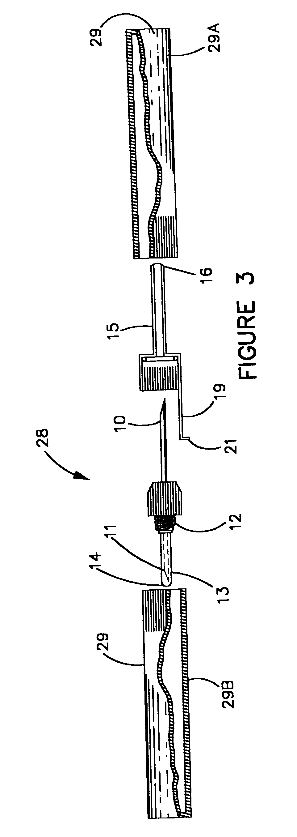
[0033] A needle 9 having a first end 10 and a second end 11 is mounted in first end 5 of shroud 4. Needle 9 should be positioned such that first end 10 of needle 9 is located outside of shroud while second end 11 of needle 9 is contained within shroud chamber 8. Needle 9 may be permanently attached to shroud 4 or it may be releasably attached. In a preferred embodiment, needle 9 is releasably attached to shroud 4 via a Luer lock 12. Luer lock 12 will facilitate the use of needles 9 of varying diameters with a single configuration of shroud 4....


PUM


Abstract

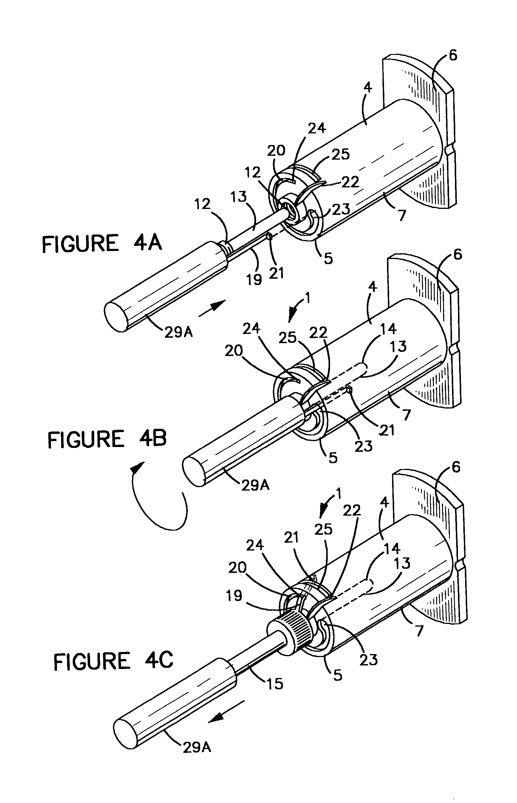
A safety syringe for a vacuum specimen tube having a stopper. The syringe includes a shroud with a double ended needle and a sheath slidably positioned over the needle's external end. The sheath's tip can be hypodermically inserted with the needle. The sheath moves between an exposed position where the sharp point of the needle's external end is exposed and a covered position where the sharp point of the needle's external end is inside the sheath. After the needle and sheath are inserted into the patient, the vacuum tube is seated in the shroud, piercing the stopper with needle's internal end and allowing blood to flow into the tube. As the tube is seated, it will also preferably engage an arm extending from the sheath to advance the sheath into the covered position. Thus, the sheath is in the covered position before the syringe is removed from the patient.

Description

PRIORITY INFORMATION[0001] This is a continuation of U.S. patent application Ser. No. 09 / 598,623, which is hereby incorporated by reference in its entirety.[0002] 1. Field of the Invention[0003] The invention relates to safety syringes in general and to blood collection safety syringes in particular.[0004] 2. Prior Art[0005] The risk of contracting diseases such as HIV or hepatitis from accidental sticks with dirty needles is a potentially deadly hazard for medical professionals. One of the most dangerous times for accidental sticks is during blood collection. This is frequently done with a syringe and one or more vacuum specimen tubes. These syringes are typically comprised of a hollow shroud having an open end and a closed end. A double pointed hollow needle is usually threaded into the closed end of the shroud such that one end of the needle is positioned outside of the shroud and the other end of the needle is positioned inside the shroud. Both ends of the needle are usually sha...

Claims


Application Information

Patent Timeline
IPC IPC(8): A61B5/15A61M5/32
CPCA61M5/3243A61B5/1444A61B5/15003A61B5/150259A61B5/150351A61B5/150389A61B5/150496A61B5/150572A61B5/150587A61B5/150648A61B5/150717A61B5/150732A61B5/154
Inventor ALEXANDER, GARY E.JOHN, THOMAS
Owner NUSAF
Learn More