System and method for monitoring locomotive operation

a technology for monitoring and operating systems, applied in the direction of engine starters, process and machine control, instruments, etc., can solve the problems of lost fuel savings, service personnel may also forget, unrealized fuel savings, etc., and achieve the effect of improving locomotive operations

Inactive Publication Date: 2002-12-05
GENERAL ELECTRIC CO
View PDF0 Cites 11 Cited by
  • Summary
  • Abstract
  • Description
  • Claims
  • Application Information

AI Technical Summary

Benefits of technology

0009] In order to solve these and other needs in the art, the inventors hereof have designed a locomotive monitoring system that preferably defines several mutually exclusive operating states. At any given time, the locomotive is deemed to be operating in one and only one of these operating states. The total amount of time that the locomotive operates in each state is preferably determined and recorded. This recorded information can then be evaluated with a view towards improving locomotive operations. For example, a plurality of mutually exclusive idle states can be defined and monitored to determine how long a locomotive idles under certain conditions instead of automatically shutting down for the purpose of conserving fuel. In this manner, the sources of lost fuel savings can be readily identified, quantified and addressed. An event log is also provided for chronicling certain operating events of interest over time, such as those relating to the starting, stopping and / or idling of the locomotive's engine.

Problems solved by technology

Although deployed AESS systems have proven reliable, the inventors hereof have discovered human factors that result in unrealized fuel savings.
Service personnel may also forget to move the ASDS to its "on" position after switching it "off" for safety during maintenance procedures.
Regardless of how or why it occurs, preventing an AESS system in a single locomotive from performing its intended function obviously results in lost fuel savings.
A related problem discovered by the inventors is unnecessary operator induced restarts, which occur, for example, when an operator moves the reverser of an automatically shutdown locomotive away from the center position.
Thus, how long each monitored parameter is out-of-range does not necessarily reveal how long such parameters as a group prevent an automatic shutdown.

Method used


Image

  • System and method for monitoring locomotive operation
  • System and method for monitoring locomotive operation
  • System and method for monitoring locomotive operation

Examples


Embodiment Construction

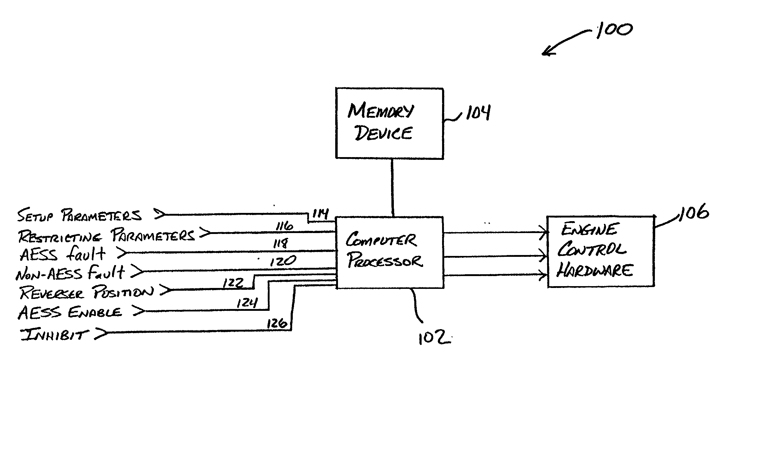
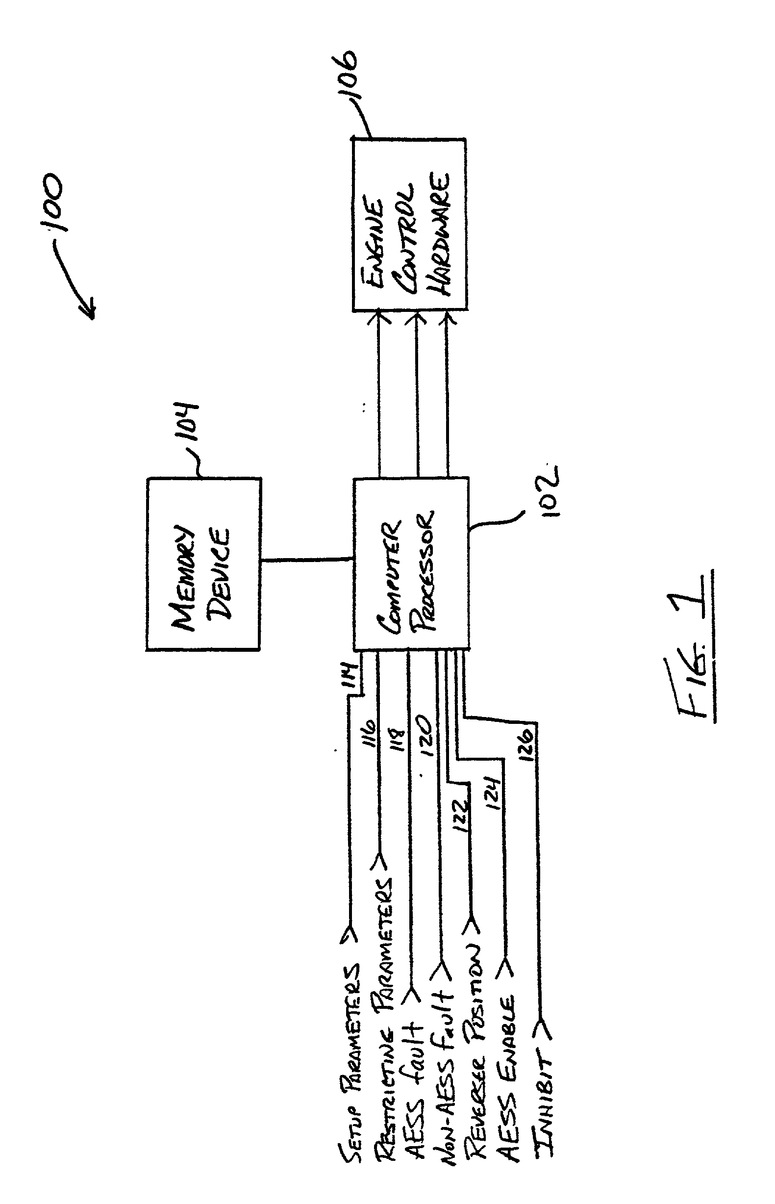
[0021] A locomotive monitoring and control system according to one preferred embodiment of the present invention is illustrated in FIG. 1 and indicated generally by reference character 100. As shown in FIG. 1, the system 100 includes a computer processor 102, a memory device 104 and engine control hardware 106. The memory device 104 may itself comprise multiple static and / or dynamic memory devices, as is common. The memory device 104 preferably stores computer instructions for execution by the computer processor 102. These computer instructions configure the computer processor 102 to monitor various locomotive operating conditions, and to output one or more commands when predefined conditions exist. The engine control hardware controls the locomotive engine (not shown) in response to commands output by the computer processor 102 including, for example, a motor command 108, a shutdown command 110, and a startup command 112. As apparent to those skilled in the art, the engine control ...


PUM


Abstract

A locomotive monitoring system defines several mutually exclusive operating states for a locomotive. The amount of time the locomotive operates in each state is preferably determined and recorded. This recorded information can then be evaluated with a view towards improving locomotive operations. For example, a plurality of mutually exclusive idle states can be defined and monitored to determine how long a locomotive idles under certain conditions instead of automatically shutting down for the purpose of conserving fuel. In this manner, the sources of lost fuel savings can be readily identified, quantified and addressed. An event log is also provided for chronicling certain operating events of interest over time, such as those relating to the starting, stopping and/or idling of the locomotive's engine.

Description

FIELD OF THE INVENTION[0001] The present invention relates to monitoring operation of a locomotive, and more particularly to monitoring the starting, stopping and / or idling of a locomotive with a view towards conserving fuel.BACKGROUND OF THE INVENTION[0002] In recent years, locomotives have been equipped with systems for automatically starting and stopping their engines when predefined conditions exist. The primary purpose of such systems is to conserve fuel, thereby lowering fuel costs while also preserving precious energy resources. For instance, a locomotive may be configured to automatically shutdown after operating a certain amount of time in parked idle so as to prevent the locomotive from needlessly wasting fuel. The locomotive may then automatically restart when, for example, an operator signals an intention to motor the locomotive, such as by moving a direction controller (known as a reverser) from a center position (that is, from a "neutral" position). A locomotive may al...

Claims


Application Information

Patent Timeline
Patent Type & Authority Applications(United States)
IPC IPC(8): H02P3/12
CPCH02P3/12Y10S477/906Y10T477/681Y10T477/70Y10T477/641Y10T74/1926
Inventor WOLF, DANIEL F.HESS, JR., GERALD JAMESCAPORALE, JR., JOHN LOUIS
Owner GENERAL ELECTRIC CO
Why Eureka
Try Eureka