Method of bending sheet metal to form three-dimensional structures

a three-dimensional structure and bending technology, applied in the field of bending sheet metal, can solve the problems of limited usefulness and high cost of curving line tooling

Inactive Publication Date: 2002-12-12
MILGO INDAL
View PDF2 Cites 149 Cited by
  • Summary
  • Abstract
  • Description
  • Claims
  • Application Information

AI Technical Summary

Benefits of technology

[0010] Another object of the invention is to provide a method for bending sheet metal along a curved bending line wherein bending stress to the metal is minimized and controlled to minimize metal fatigue and distortion.
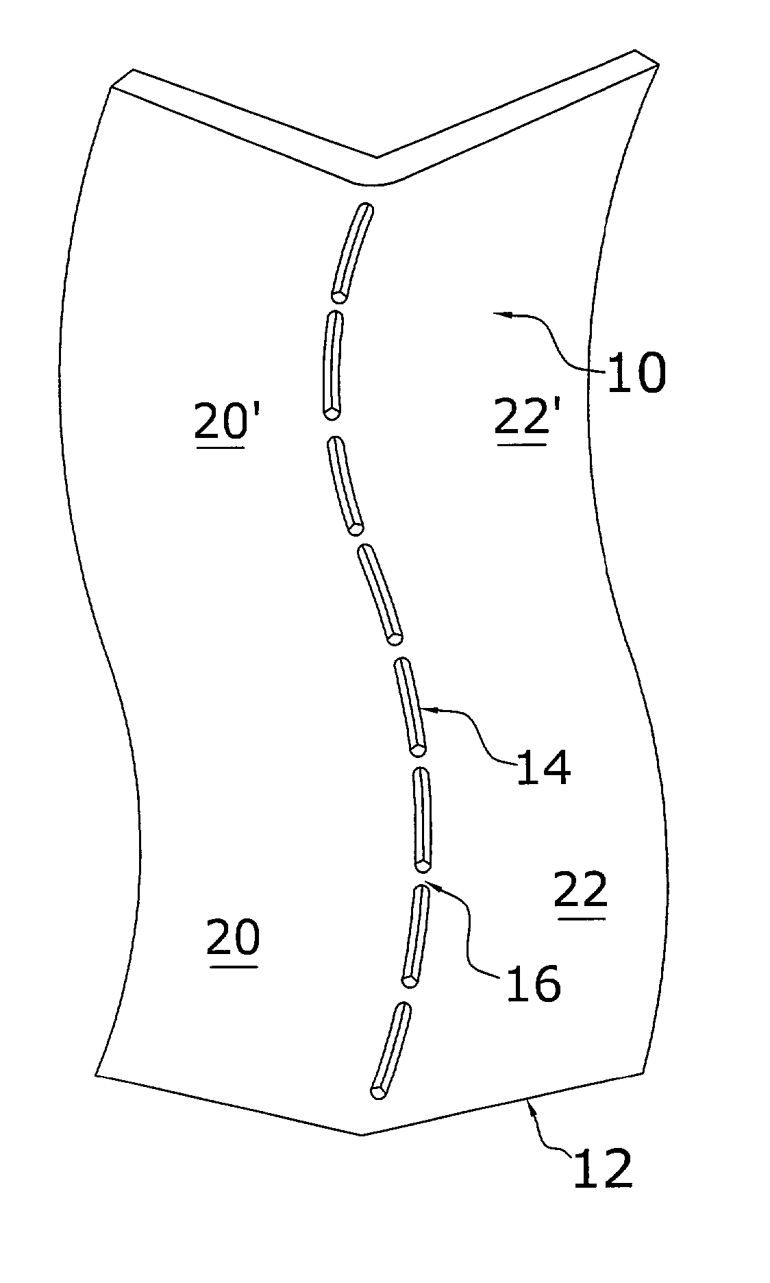
[0012] Accordingly, a method for bending sheet metal is disclosed which includes introducing to the sheet metal thinned regions which are positioned either along or immediately adjacent to the bending line. These thinned regions allow the metal to be easily bent along the bending line using conventional hand tools or non specialized machines. The thinned regions are preferably shaped as slots cutting through the metal and having a specific width, length, end shape, and spacing from each adjacent slot. In some instances, the slots have a depth into the metal sheet. In other instances, the thinned regions with a depth are continuous.
[0015] According to a third embodiment, a continuous thinned region that has a depth less than the thickness of the metal is used instead of interrupted aligned or staggered slots. This has aesthetic as well as practical advantages since there are no cut regions that need to filled in.
[0016] The thinned regions may be introduced into the metal sheet using conventional machines or computer-driven machines such as a laser cutting machine or a water jet-cutting machine or other softwareware-driven devices which enable grooving or selective weakening of metal through other means. These machines are capable of either cutting completely through the metal sheet, or just etching the thinned regions only partially through the metal sheet, as required. Also, these machines are capable of accurately cutting along lines which may be straight and / or curved.

Problems solved by technology

Not only is this curve-line tooling costly and time-consuming, customizing it to the particular bend, the resulting tooling is also unique to each specific curve, and therefore may have a limited usefulness (i.e., only useful in bending a piece of metal along one specific shape curve).

Method used


Image

  • Method of bending sheet metal to form three-dimensional structures
  • Method of bending sheet metal to form three-dimensional structures
  • Method of bending sheet metal to form three-dimensional structures

Examples


Embodiment Construction

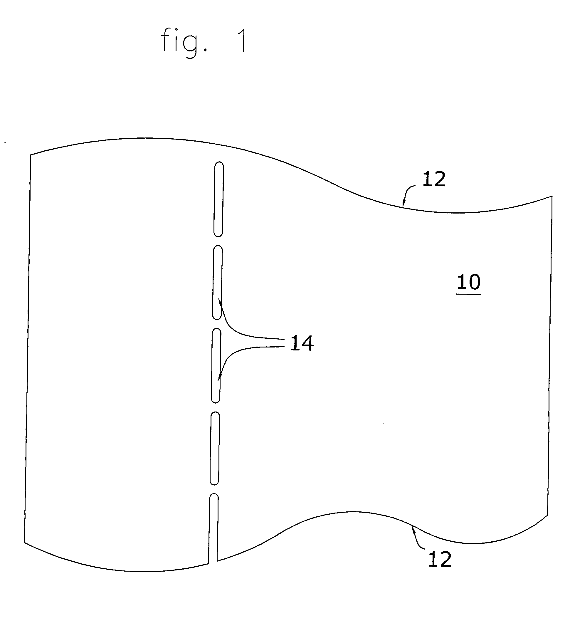
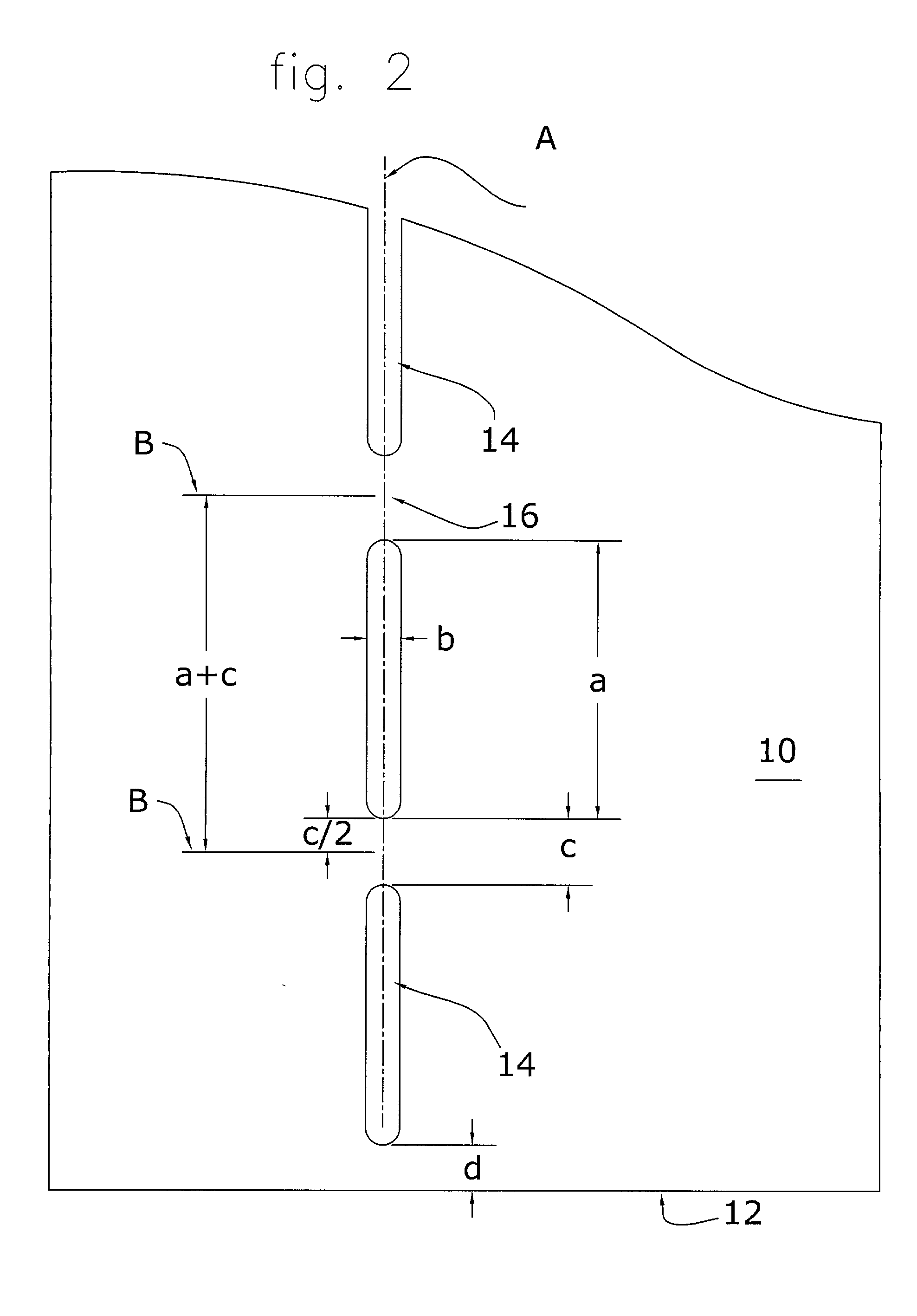
[0049] Referring to FIGS. 1 and 2, a partial plan view of a metal sheet 10 having an edge 12 is shown including a bending line (or score line) "A", and a plurality of thinned regions 14, shown as slots in these figures. According to this first embodiment, a single "aligned" row of thinned regions (slots) 14 is formed into metal sheet 10 directly along bending line A. According to this embodiment, thinned regions 14 are cut entirely through metal sheet 10, and thereby collectively form a perforated line which is coaxial with bending line A.

[0050] Thinned regions 14 in this embodiment have a length equal to "a" (in FIG. 2), a width equal to "b", and are spaced from each other a distance equal to "c", defining intermediate connections 16 which are located between any two adjacent thinned regions 12. Intermediate connections 16 function literally as hinges about which the metal sheet on either side of the bending line A may bend. The distance b has a minimum determined by k thickness, t...


PUM

PropertyMeasurementUnit
angleaaaaaaaaaa
thicknessaaaaaaaaaa
thicknessaaaaaaaaaa

Abstract

A method for bending sheet metal includes introducing to the sheet metal thinned regions which are positioned either along or immediately adjacent to a bending line. These thinned regions allow the metal to be easily bent along the bending line using conventional hand tools or non-specialized machines. The thinned regions may be shaped as slots having a specific width, length, end shape, spacing from each adjacent slot, and depth into the metal sheet. According to one embodiment of the invention, each slot is cut through the entire thickness of the metal sheet. Other related embodiments require that the slots be only partially cut or etched thereby having a depth that is less than the thickness of the metal sheet. The thinned regions may be any appropriate shape as controlled by the shape of the bend, the type of metal, the thickness of the metal, the ductility of the metal, the angle of the bend, and the application of the metal (e.g., load bearing, etc). According to a second embodiment, two generally parallel sets of thinned regions are formed adjacent and generally parallel to the bending line. In a preferred application, the two sets of thinned regions are slots (cutting through the metal) and are staggered or offset with respect to each other.

Description

[0001] This application is a continuation-in-part of patent application having Ser. No. 09 / 492,994, filed Jan. 27, 2000 which claims priority from provisional patent application, filed Jan. 27, 1999 having Serial No. 60 / 117,566, the disclosure of which is hereby incorporated by reference.[0002] 1) Field of the Invention[0003] This invention generally relates to methods for shaping and forming malleable sheet material (e.g., metal sheet), and, more particularly, to a method for bending sheet metal along either straight or curved score lines.[0004] 2) Description of the Prior Art[0005] Sheet metal is a commonly used material for a multitude of applications including housings and casings, interior and exterior structures, and various covers and supports. Stock sheet metal is typically supplied to manufactures in the form of flat sheets or rolls of flat stock. The manufacturer uses the stock metal sheet and cuts, shapes, and bends the metal, as necessary, to manufacture various products...

Claims


Application Information

Patent Timeline
Patent Type & Authority Applications(United States)
IPC IPC(8): B21D5/00B21D11/20
CPCB21D5/00B21D11/20B21D11/08
Inventor GITLIN, BRUCEKVETON, ALEXANDERLALVANI, HARESH
Owner MILGO INDAL
Why Eureka
Try Eureka