
Outlet device for a jet engine

a jet engine and outlet device technology, applied in the direction of jet propulsion plants, machines/engines, spraying apparatuses, etc., can solve the problem that the manoeuvring possibilities that may be obtained by such conventional rudders may be insufficien

Inactive Publication Date: 2002-12-19
SAAB AB
View PDF4 Cites 24 Cited by
  • Summary
  • Abstract
  • Description
  • Claims
  • Application Information

AI Technical Summary

Benefits of technology

[0007] By designing the outlet with two separate outlet portions, it is possible to obtain a jet which has a stabilising effect on the flying of an aircraft. Depending on the direction of the outlet flows from both the outlet portions a certain tipping moment and rolling moment may be obtained. By such an outlet device, it is thus possible to replace the corresponding dynamic rudders of a conventional aeroplane and in such a way obtain a simplified aeroplane design. It is possible, by means of the outlet flows, to provide determined moving moments of an aeroplane, for instance yaw moment, tipping moment or rolling moment. Thereby, said control means of said outlet portions may function as the elevator of the aeroplane and thus steering the aeroplane in a vertical direction, and as the side rudder of the aeroplane and thus steering the aeroplane in a horizontal direction. By directing one of the outlet flows obliquely upwardly and the other outlet flow obliquely downwardly, a rolling moment may be obtained, for instance. Except for the fact that such an outlet device gives the tail portion of the aeroplane a simplified design, a very good authority of the steering is obtained by such a control, i e the aeroplane will respond very well to changes in the direction of the outlet flows. Furthermore, such a control in a vertical direction is very useful when an aeroplane is propelled at relatively low speeds.
[0011] According to a further embodiment of the invention, a said control means includes at least one guide flap of each outlet portion. Said guide flap is preferably rotatable about an axis, which extends substantially across the flow direction. Advantageously, said control means may include at least two guide flaps of each outlet portion, wherein the rotary axis of one of the guide flaps extends substantially in parallel with the rotary axis of the other guide flap. The two guide flaps may be provided at a distance from each other and arranged to enclose the outlet flow concerned between each other. In such a way one may in an efficient manner control the outlet flow in a desired direction which may form an angle with the flow direction. Said outlet portion may also include at least a third guide flap, which is provided between the two guide flaps and which is rotatable about a rotary axis, which extends substantially in parallel with the rotary axis of the two guide flaps.

Problems solved by technology

Such a tail portion involves a complicated design work for obtaining the desired aerodynamic properties and manoeuvring possibilities of the aeroplane.
Furthermore, the manoeuvring possibilities which may be obtained by such conventional rudders may be experienced to be insufficient, in particular if the aeroplane is propelled at a low speed.

Method used


Image

  • Outlet device for a jet engine
  • Outlet device for a jet engine
  • Outlet device for a jet engine

Examples


Embodiment Construction

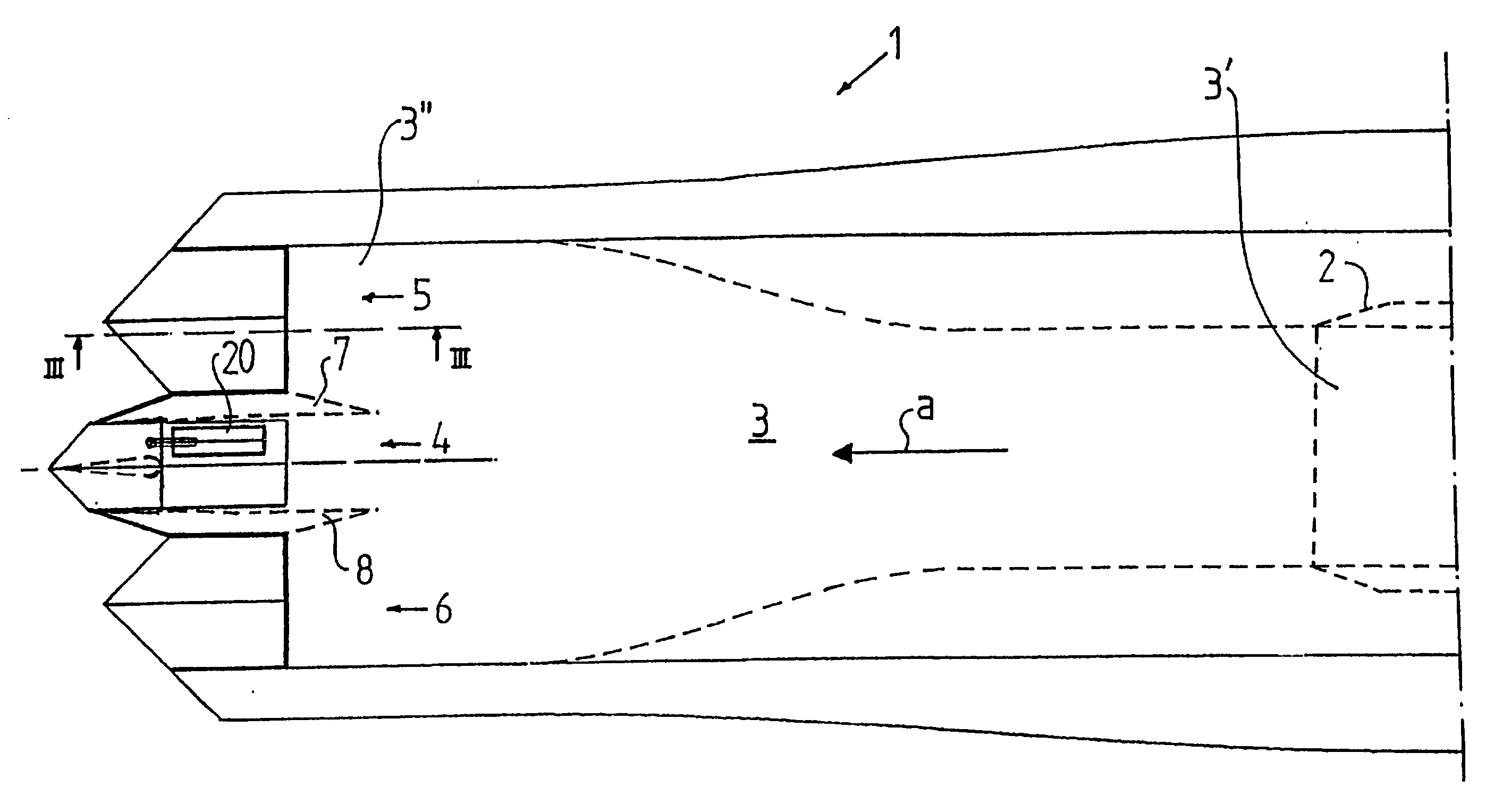
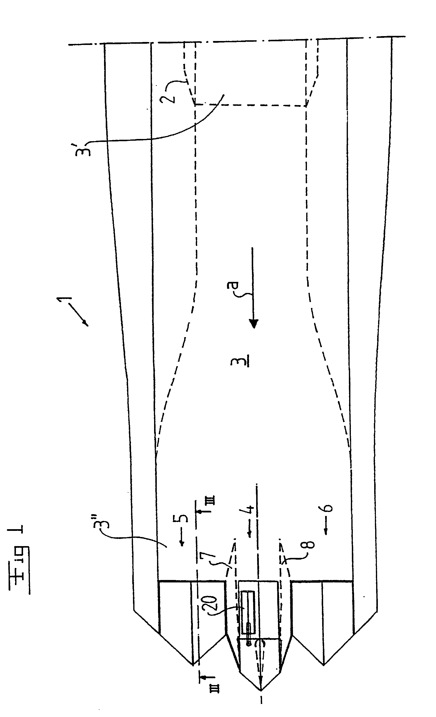
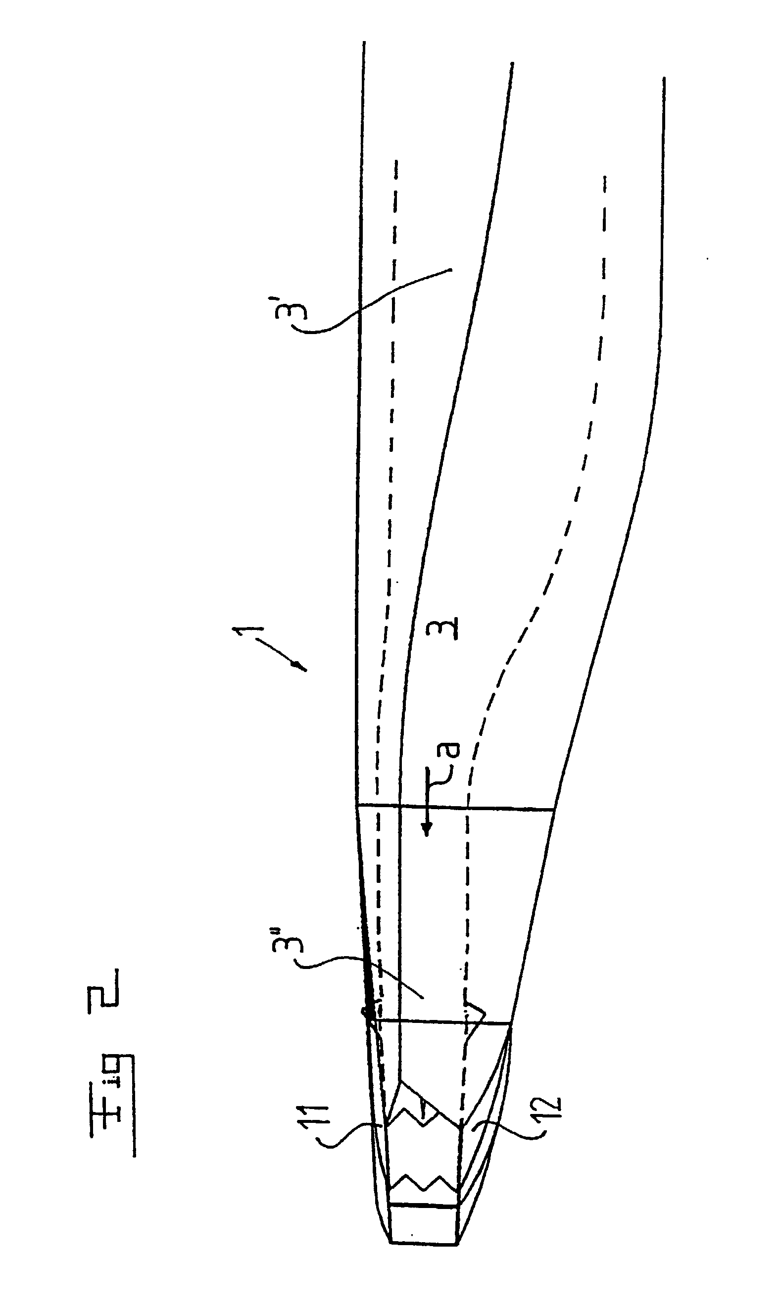
[0019] FIGS. 1 and 2 disclose a tail portion of an aircraft 1. The aircraft 1 includes a partly indicated jet engine 2, which is arranged to produce a jet for the propelling of the aircraft 1. The jet engine 2 connects to an outlet channel 3, which has an upstream end 3' in the proximity of the jet engine 2 and a downstream end 3", the outlet channel 3 defines a main flow direction a for the jet. The upstream end 3' of the outlet channel 3, which connects to the jet engine 2, preferably has a substantially circular shape, seen in a section across the flow direction a. At the downstream end 3", the outlet channel 3 has an elongated shape seen in a section across the flow direction a.

[0020] At the downstream end 3", the outlet channel 3 is divided into three outlet portions lying beside each other, and more exactly a central outlet portion 4 and two lateral outlet portions 5, 6, which are arranged at a respective side of the central outlet portion 4. The outlet portions 4-6 are separa...


PUM


Abstract

An outlet device for a jet engine (2) includes an outlet channel (3), which has an upstream end (3') for being connected to the jet engine and a downstream end (3'') and which defines a main flow direction (a) for a jet from the jet engine. The outlet channel has in the proximity of the downstream end an elongated shape, seen in a section across the flow direction, and includes at least two outlet portions (4, 5, 6), which are separated from each other, for a respective outlet flow of said jet. A first outlet portion (5, 6) includes means for controlling the outlet direction of the outlet flow in a first plane and a second outlet portion (4) includes means for controlling the outlet direction of the outlet flow in a second plane, which forms an angle to the first plane. An aircraft may include such an outlet device.

Description

THE BACKGROUND OF THE INVENTION AND PRIOR ART[0001] The present invention refers to an outlet device for a jet engine, including an outlet channel, which defines a main flow direction for a jet from the jet engine, wherein the outlet channel has an upstream end for being connected to the jet engine and a downstream end, wherein the outlet channel in the proximity of the downstream end has an elongated shape, seen in the flow direction, and includes at least two outlet portions, which are separated from each other, for a respective outlet flow of said jet. The invention also refers to an aircraft including a jet engine.[0002] Typical aeroplanes, which are driven by one or several jet engines, beside the forward wings today frequently have a tail portion with a fin and two stabilising wings. On the fin a side rudder is normally provided for the steering of the aeroplane in a lateral direction. On the stabilising wings, or in certain cases on the main wings for instance on so called de...

Claims


Application Information

Patent Timeline
IPC IPC(8): F02K1/00F02K1/12
CPCF02K1/002F02K1/1207F02K1/008
Inventor WEILAND, CARLERICBERGLUND, HANS
Owner SAAB AB
Learn More