
Single push-button type storage case for compact discs

Inactive Publication Date: 2003-01-23
CHU YUK LUNG
View PDF0 Cites 11 Cited by
  • Summary
  • Abstract
  • Description
  • Claims
  • Application Information

AI Technical Summary

Benefits of technology

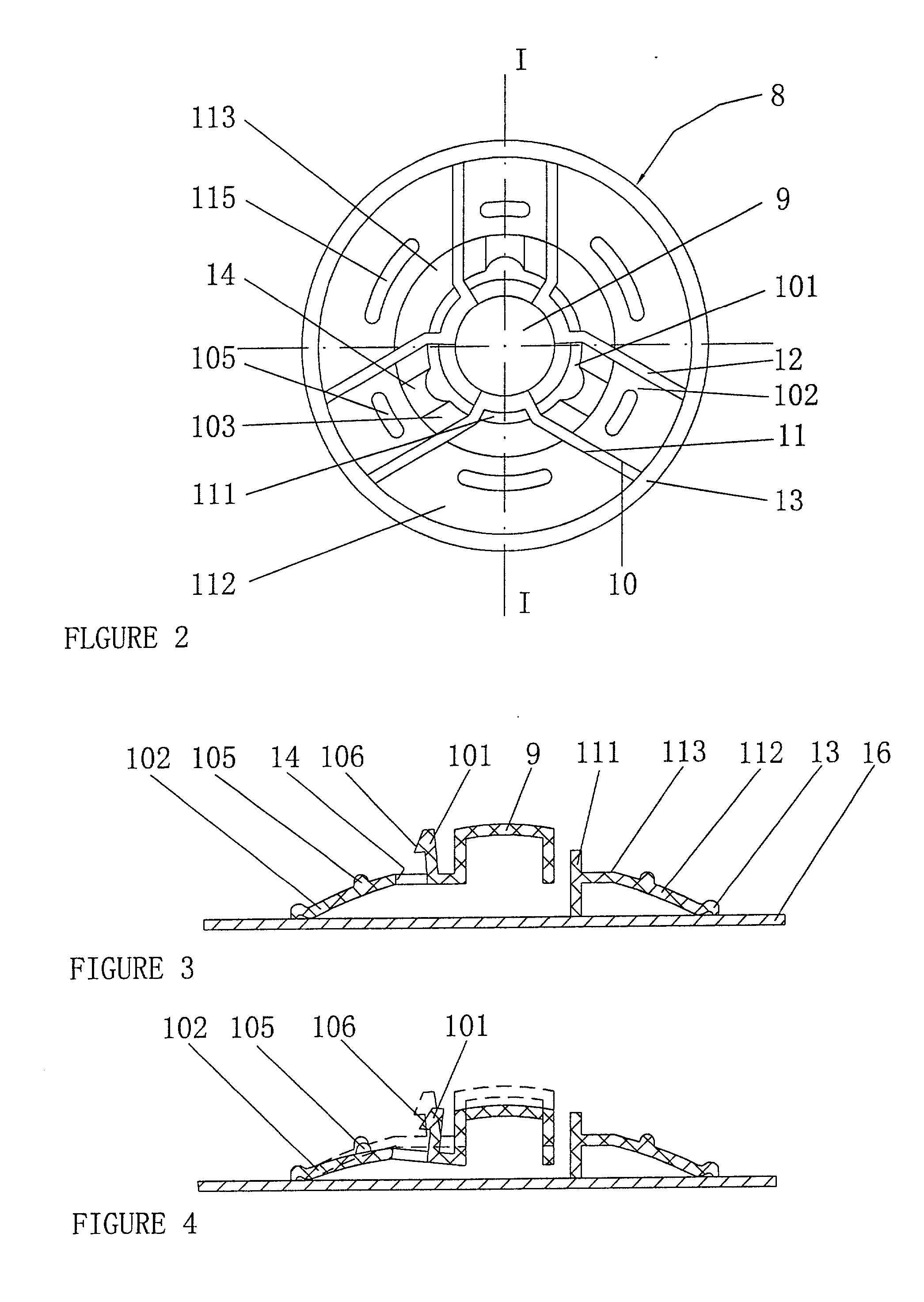
[0012] The inner bottom further is provided with a second collar flange which is connected with the rear ends of the spring-arms and the supporting plates. In a sense, the provision or setting up of the second collar flange can increase the torsional elasticity of the spring arm.
[0013] On first plane portion of each spring-catch, there is provided an opening respectively, so that spring-arms are easy to be deformed elastically.
[0016] The outer surface of the storage case is covered a thin film so that the cleanness of the inside of the storage case can be maintained. In the present invention, the storage case and the film are made of plastic material.
[0017] The advantage of the structure according to the present invention lies in that a single piece of push-button can be used to press on the spring-catches of the central retaining element so that the first projecting portions and spring arms can bend downwardly about the bottom ends or rear ends of the spring arms thereby the locking or stopping state between the first projecting portion and the clearance of the disc can be released or separated and at the same time when the finger of a user is released from the push-button, the disc can be lifted upwards following the lifting of the projections of the first projecting portions, thereby the disc, after being released from locking, can be raised with stability, instead of rapid and abrupt lifting and possibly a certain spring-catch is in unreleased state as with the prior art storage case. The pivoting point or the support point for rotation is situated on the end of the spring arm, when bent, the pivoting or rotating arm is relatively longer, so that the pressing force needed for pressing the single push-button can be reduced, this results in easy or convenient use as well as longer service life of the storage case.

Problems solved by technology

This connection is frequently so tight that the disc can only be removed from the storage case by a user who applies an adequate or sufficient pressure on the spring-catches.
However, sometime, it is impossible to remove the disc.
Due to the face that the central retaining element of the above mentioned patent has been designed to have the_push-button divided into several pieces or parts by radial slits and spring-catches which are formed by collar projecting, when a user presses on such push-button, the spring-catches and the lifting elements must be made to rotate about the support arms, however there is only a limited range or distance for the support arms to be optimumly positioned in the base member, thereby the support arms can only be spaced a short distance from the spring-catches, therefore a user, when pressing on such push-button having several pieces or parts, must make greater effort to lift and move the disc from its storage case.
In addition, since the push-button has several pieces or parts, often, the finger of a user can not press simultaneously on all pieces or parts of such push-button, therefore the disc may not be removed even if a greater effort is made, because a certain piece or part is not pressed down by the finger, and in this case, the damage of the surface of the disc may occur.
The applicant of the prior art patent has designed a separate press head inserted in the center of the central retaining element to overcome the above mentioned drawback that all pieces or parts of the push-button cannot be simultaneously pressed, the result is that not only the structure of the storage case becomes correspondingly complicated, and more effort is needed to press down such push-buttons but also, the above-mentioned drawback still can not be completely eliminated.

Method used


Image

  • Single push-button type storage case for compact discs
  • Single push-button type storage case for compact discs
  • Single push-button type storage case for compact discs

Examples


Embodiment Construction

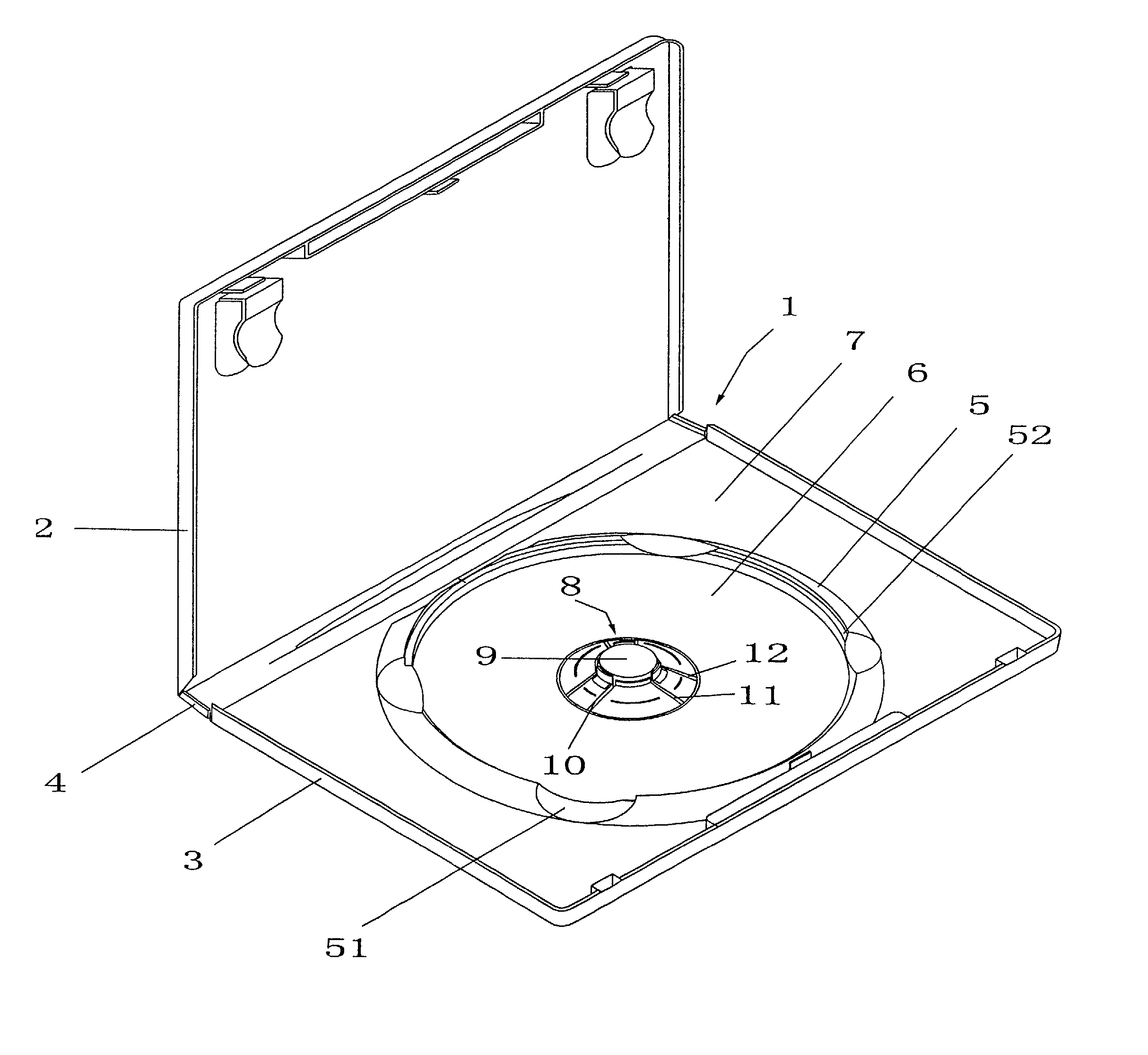
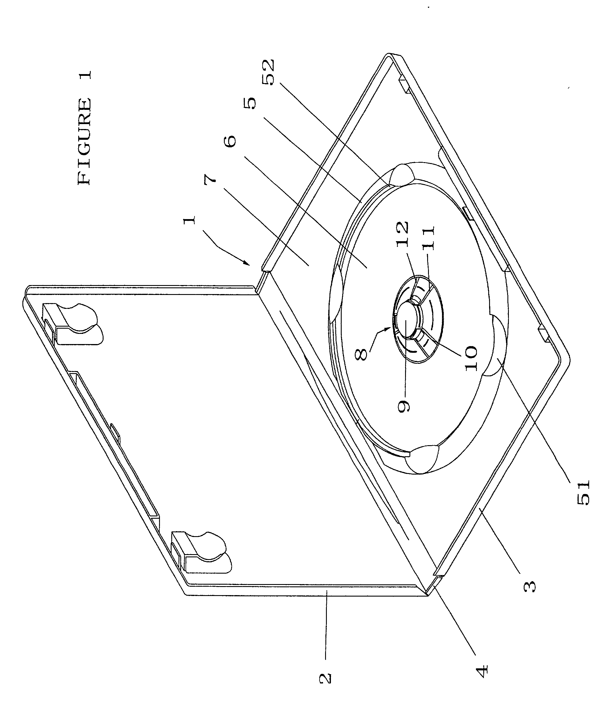
[0023] Referring to FIG. 1 and FIG. 2, a single push-button type storage case 1 for a disk-shaped information carrier, hereafter referred to as a compact disc (CD), has a lid 2, a base 3 and a joint edge 4, the lid 2 and the base 3 are integrated by the joint edge 4. The central portion of the base 3 is provided with a first collar flange 5 which is provided with curved recesses 51 on it, into which the edge of an inserted CD extends slightly and thereby can be held by a hand, between the thumb and index finger. The base 3 is divided into an inner bottom 6 and an outside bottom 7 by the first collar flange 5. The inner bottom 6 of the first collar flange 5 is configured to surround the inserted CD around the peripheral edge. Preferably, the inner surfaces of the first collar flange 5 is a step-shaped area 52, so that the outer peripheral edge of the inserted CD can placed on the step surface of the stepped surface area 52.

[0024] The first collar flange 5 is provided with a central s...


PUM


Abstract

The present invention relates to a storage case having a central retaining element which comprises a push-button, at least two spring-catches forming a locking element, and at least two supporting clips forming a supporting element. Each spring-catch has a first projecting portion with a projection and a spring-arm and each supporting clip has a second projecting portion and a supporting plate. The spring-arms and the supporting plates are tilted down to form a conical seat. The spring-catches and the supporting clips are spaced by means of the spacing slits. The push-button is placed in the central hole defined by spring-catches and integrated with the underside of spring-catches. When a pressure applied on the push-button is released, the projection will make its outside tilted surfaces to lift the disc from the supporting surface. As such, the user can readily remove the CD.

Description

[0001] The present invention relates to a single push-button type storage case for compact discs.BACKGRAOUD OF THE INVENTION[0002] 1. Field of the Invention[0003] The present invention relates to a storage case for a disc-shaped information carrier for an optically readable digital audio-disc otherwise known as a compact disc or CD. The disc has a central clearance for it to be clipped or kept in the case. More particularly, the present invention relates to a single push-button type storage case. The storage case has a base and a collar flange on the base. The collar flange is substantially fitted to the outline of the disc and in the center of the collar flange, there is provided a central retaining element. The central retaining element has spring-catches and supporting clips, of which projecting portions pass through the central clearance of the disc. The spring-catches are connected with the pushbutton and act as a locking element of the disc which overlaps with a thickness of t...

Claims


Application Information

Patent Timeline
IPC IPC(8): G11B33/04
CPCG11B33/0427
Inventor CHU, YUK LUNG
Owner CHU YUK LUNG
Learn More