Drilling bit without resharpening, non-resharpening blade, and drilling bit main body

A drill bit and blade technology, applied in drilling/drilling equipment, shovel drill, drill repair, etc., can solve the problems of insufficient alignment accuracy, difficulty in firmly holding the blade 5, and difficulty in adhering to it, and achieve the goal of maintaining the accuracy of shaft vibration Effect

Inactive Publication Date: 2004-09-08
MITSUBISHI MATERIALS CORP
View PDF1 Cites 9 Cited by
  • Summary
  • Abstract
  • Description
  • Claims
  • Application Information

AI Technical Summary

Problems solved by technology

[0014] Thereby, among the pair of outer surfaces 5A of the insert 5, the part toward the rear of the drill bit rotation direction T is difficult to be closely attached to the pair of inner surfaces 4A of the insert mounting seat 4. The mounting seat 4 is held, and even as mentioned above, the structure in which the protrusion 7 and the guide groove 6 are engaged with each other is adopted, and the alignment accuracy of the blade 5 with respect to the drill body 1 is still insufficient.

Method used


Image

  • Drilling bit without resharpening, non-resharpening blade, and drilling bit main body
  • Drilling bit without resharpening, non-resharpening blade, and drilling bit main body
  • Drilling bit without resharpening, non-resharpening blade, and drilling bit main body

Examples


Embodiment Construction

[0052] Embodiments of the present invention will be described below with reference to the drawings.

[0053] Figure 1 to Figure 5 It represents the first embodiment of the present invention.

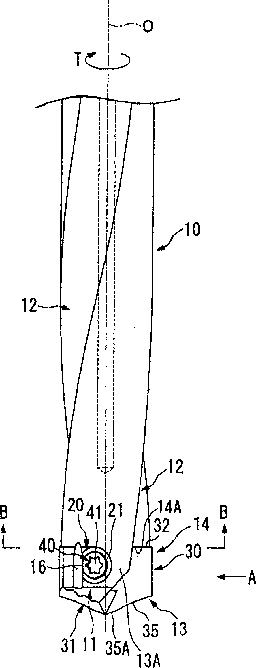
[0054] The drill body 10 of the throwaway drill of this embodiment is reduced in diameter with respect to the drill pipe tail (not shown) integrally formed on its rear end side, and as a whole constitutes a drill body 10 that rotates around the axis O and rotates around the axis O. Centered multistage cylinder.

[0055] A pair of chip discharge grooves 12 opened on the front end surface 11 of the drill body 10 are formed on the outer periphery of the front end side portion of the drill body 10, and the discharge grooves 12 are on mutually opposite sides of the clamping axis O so as to move toward the axis O. The rear end side of the drill bit is twisted backward in the direction of rotation T of the drill to form a helical shape.

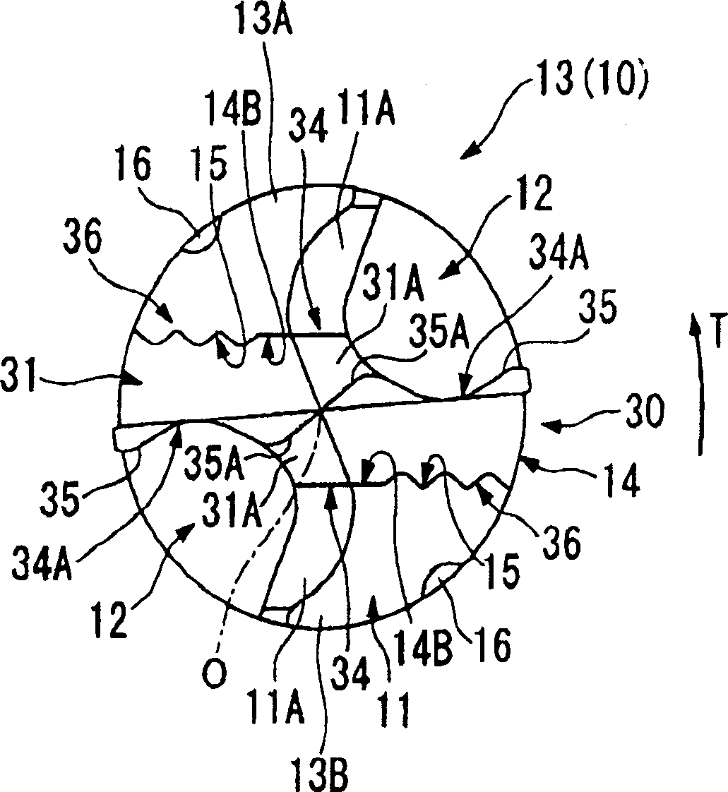
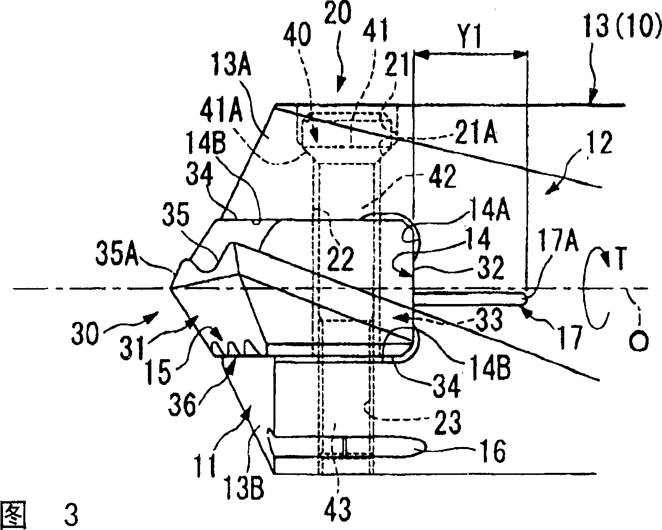
[0056] In addition, on the front end portion 13 of t...


PUM

PropertyMeasurementUnit
angleaaaaaaaaaa

Abstract

In a throw-away tipped drill, a slit (17) is formed at the bottom surface of a tip attachment seat (14) which faces towards the end of its axial line direction (O), with this slit (17) extending towards the rear of the axial line direction (O). Furthermore, when seen from the end of the axial line direction (O), this slit (17) is arranged as being displaced so as to be closer to a second end portion into which a shaft portion of a clamp bolt is threaded than to a first end portion which is pressed by a head portion of that clamp bolt. As a result, when, using the clamp bolt, the pair of outer side surfaces of the tip are pressed by the pair of internal side surfaces of the tip attachment seat (14), the pressing forces are mutually equal to one another.

Description

technical field [0001] The present invention relates to a throw-away type that detachably mounts a substantially flat throw-away insert (hereinafter referred to as insert) having a cutting edge at the front end to a groove-shaped insert mounting seat formed at the front end of the drill body. drill. Background technique [0002] An example of such throwaway drills is disclosed in Japanese Unexamined Patent Publication No. 11-197923, for example. In this kind of drill, a circular hole is formed on the bottom surface of a groove-shaped insert mounting seat opened on the front end surface of the drill body, and a hole that can be inserted is provided on the rear end surface of a substantially flat blade mounted on the insert mounting seat. to the shaft portion inside the above-mentioned circular hole. Simultaneously, by inserting the shaft portion into the circular hole, the engaging member protruding from the inner periphery of the circular hole is engaged with the notch for...

Claims


Application Information

Patent Timeline
Patent Type & Authority Applications(China)
IPC IPC(8): B23B51/00B23B51/02B23B51/04
CPCB23B2251/02B23B51/0009Y10S408/713B23B2270/08B23B2260/016B23B2251/50B23B51/048B23B51/02B23B2260/132Y10T408/909Y10T408/9097Y10T408/90993B23B51/00035B23B51/00
Inventor 泷口正治
Owner MITSUBISHI MATERIALS CORP
Why Eureka
Try Eureka