Crankshaft bearing for internal combustion engine

a crankshaft bearing and internal combustion engine technology, applied in the direction of sliding contact bearings, rigid support of bearing units, mechanical apparatus, etc., can solve the problems of large repetitive fluctuation load applied to the bearing housing, deformation or breakage of the tabs and the notches, and interference with one another, so as to enhance the output power of internal combustion engines, and reduce the weight of internal combustion engines

Active Publication Date: 2012-09-27
DAIDO METAL CO LTD
View PDF10 Cites 10 Cited by
  • Summary
  • Abstract
  • Description
  • Claims
  • Application Information

AI Technical Summary

Benefits of technology

[0010]As the trend of recent years, the output power of internal combustion engines is enhanced, and rigidity of the bearing housings of the crankshafts tends to be lowered in order to reduce the weights of the internal combustion engines. In association with this, the bearing housings are easily deformed elastically, and there arises the problem that at the time of operation of the internal combustion engines, the tabs of the semicircular thrust bearings and the notches of the semi-cylindrical sliding bearings repeatedly interfere with one another, and the tabs and the notches are deformed or broken.

Problems solved by technology

In association with this, the bearing housings are easily deformed elastically, and there arises the problem that at the time of operation of the internal combustion engines, the tabs of the semicircular thrust bearings and the notches of the semi-cylindrical sliding bearings repeatedly interfere with one another, and the tabs and the notches are deformed or broken.
When the crankshaft revolves at a high speed in the operation of an internal combustion engine, a large repetitive fluctuating load is applied to the bearing housing.
As a result, the tabs of the semicircular thrust bearing and the side edges of the notches of the semi-cylindrical sliding bearing collide with one another and strongly interfere with one another.

Method used


Image

  • Crankshaft bearing for internal combustion engine
  • Crankshaft bearing for internal combustion engine
  • Crankshaft bearing for internal combustion engine

Examples


Embodiment Construction

[0054]Hereinafter, an embodiment of the present invention will be described with reference to the accompanying drawings.

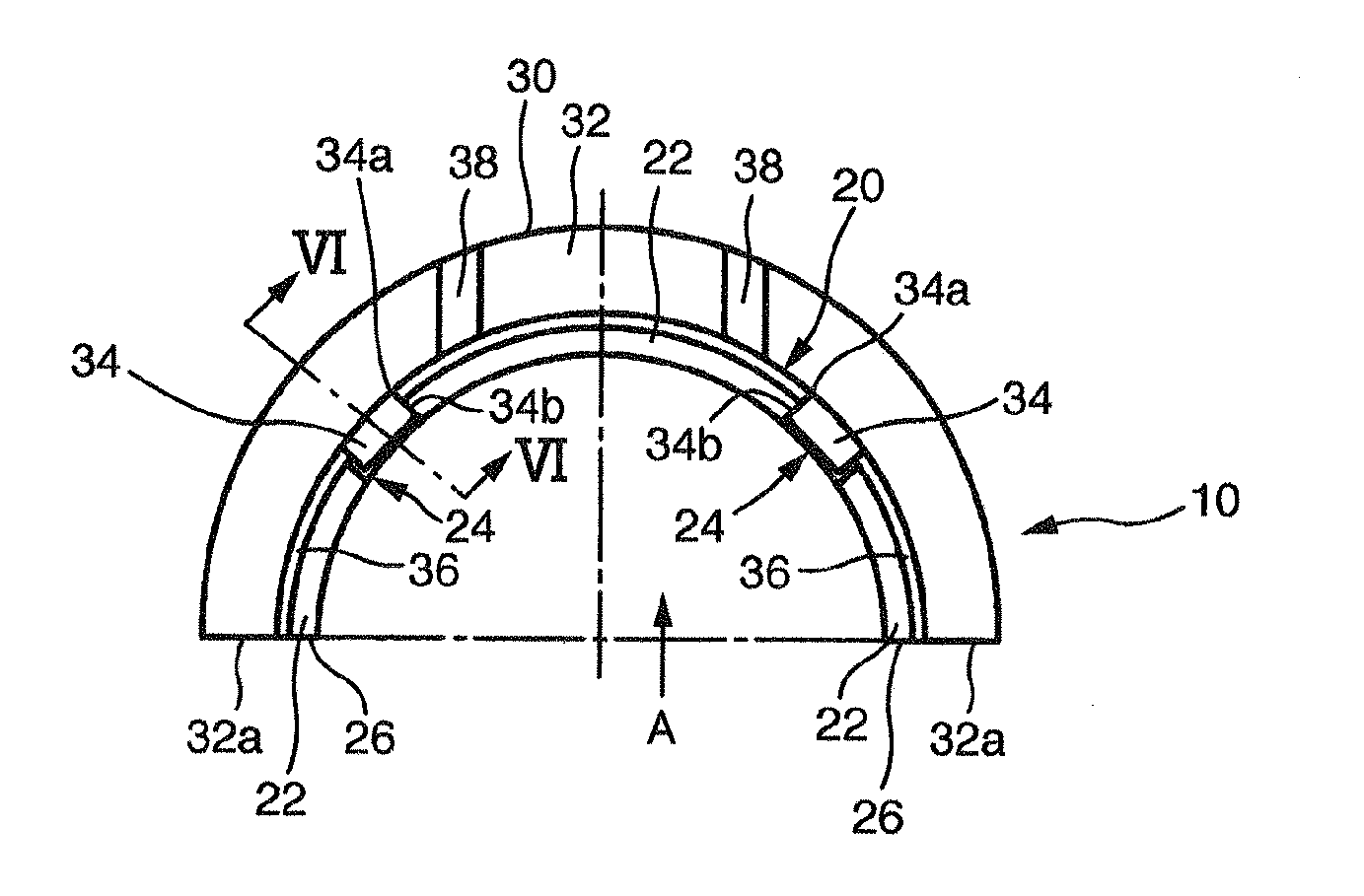
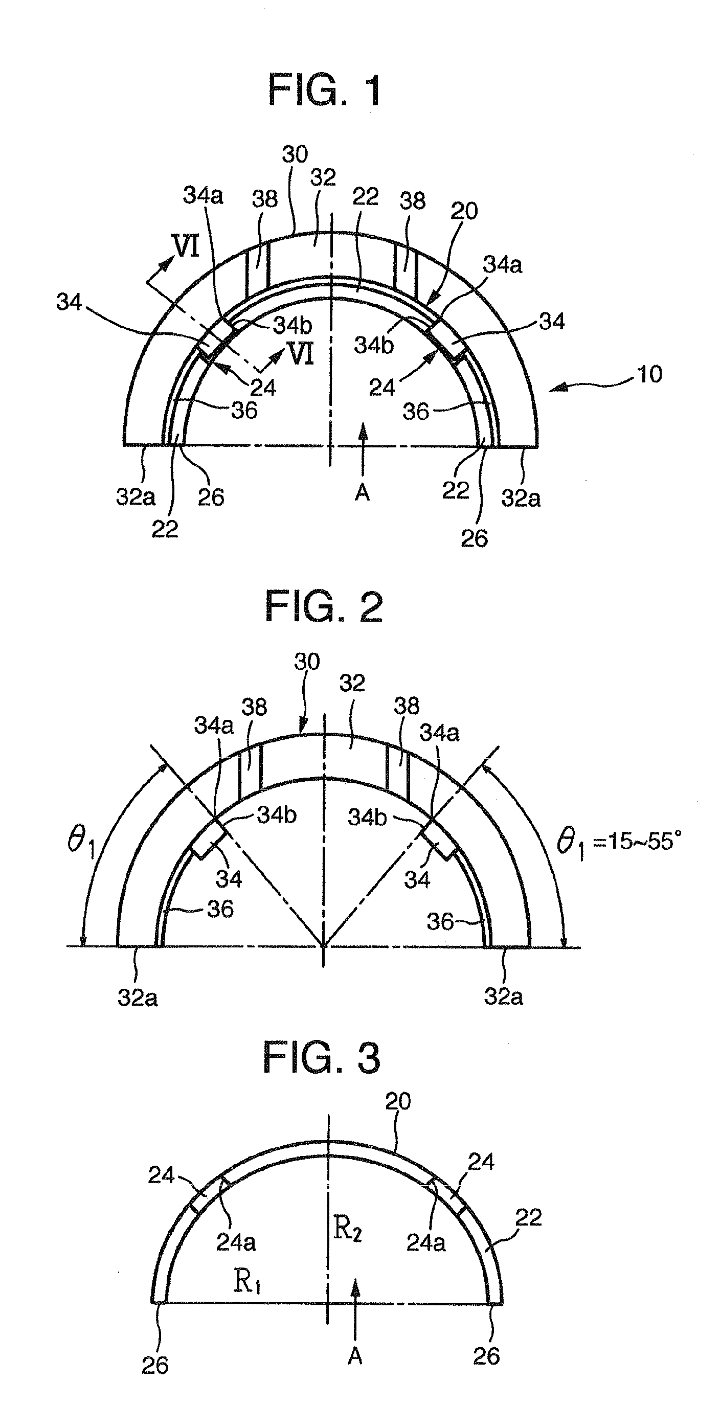
[0055]FIG. 1 shows a half body 10 of a crankshaft bearing for an internal combustion engine according to one embodiment of the present invention. The half body 10 is constituted of a semi-cylindrical sliding bearing 20 and a semicircular thrust bearing 30 which are in a combination relation with each other. The semicircular thrust bearings 30 are provided along both end surfaces 22 (that is, both ends in an axial direction or a width direction) of the semi-cylindrical sliding bearing 20 to be formed into a pair of flange shapes (however, in the drawings, only one of the semicircular thrust bearings 30 is shown). In the present embodiment, the configuration is adopted in which a pair of semicircular thrust bearings 30 is attached to the semi-cylindrical sliding bearing 20. However, a single semicircular thrust bearing may be attached to a semi-cylindrical sliding be...


PUM


Abstract

Disclosed is a crankshaft bearing for an internal combustion engine. At the inner periphery of the semicircular thrust bearing, two impact load receiving projections are projected besides the two tabs. Each of at least the two impact load receiving projections is between each of the two tabs and each of the circumferential end surfaces of the semicircular thrust bearing. The two impact load receiving projections are at line-symmetrical positions with each other with respect to the center line of the semicircular thrust bearing. A height of the impact load receiving projection is set at a dimension such that a top portion of the impact load receiving projection is not in contact with an outer circumferential surface of the semi-cylindrical sliding bearing in a static state in which the pair of semi-cylindrical sliding bearings is assembled into the bearing housing of the crankshaft and restrained.

Description

[0001]INCORPORATION BY REFERENCE[0002]The present application claims priority from JP Patent Application Ser. No. 2011-67854 filed on Mar. 25, 2011, the content of which is hereby incorporated by reference into this application.BACKGROUND OF THE INVENTION[0003](1) Field of the Invention[0004]The present invention relates to a crankshaft bearing for an internal combustion engine, and more particularly relates to a crankshaft bearing that is used with a semicircular thrust bearing attached to each of a pair of semi-cylindrical sliding bearings that is to be combined into a cylindrical shape.[0005](2) Description of Related Art[0006]A crankshaft of an internal combustion engine is supported at a journal portion thereof by a lower portion of a cylinder block of the internal combustion engine via a main bearing constituted of a pair of semi-cylindrical sliding bearings. Out of the pair of semi-cylindrical sliding bearings, one or both of the semi-cylindrical sliding bearings is or are us...

Claims


Application Information

Patent Timeline
Patent Type & Authority Applications(United States)
IPC IPC(8): F16C17/10F16C35/02
CPCF16C43/02F16C17/10F16C9/02F16C33/08F16C2226/76F16C2240/30F16C2360/22F16C33/04
Inventor KUWABARA, AISUKEMIZUNO, TAKAHIKO
Owner DAIDO METAL CO LTD
Why Eureka
Try Eureka