Chuck

a technology of chuck and chuck body, which is applied in the field of chuck, can solve the problems of inability to accurately cut, and achieve the effects of reducing friction resistance, preventing deformation, and preventing adverse effects of torsional deformation

Active Publication Date: 2005-04-07
NIKKEN KOSAKUSHO WORKS LTD
View PDF14 Cites 9 Cited by
  • Summary
  • Abstract
  • Description
  • Claims
  • Application Information

AI Technical Summary

Benefits of technology

[0013] The present invention has been accomplished to solve the above-mentioned problems, and an object of the invention is to provide a chuck which can prevent torsional deformation of a chuck sleeve, which would otherwise occur because of excessive tightening of a clamp sleeve against the chuck sleeve, to thereby eliminate adverse effects of the torsional deformation on the chuck sleeve, which in turn prevents deflective vibration in the chuck sleeve, which is a portion of a tool holder, to thereby improve machining accuracy.
[0019] Preferably, at least one of opposite surfaces of the thrust member is surface treated so as to reduce friction resistance produced when the end surface of the clamp sleeve comes into contact with the thrust member.
[0020] In the chuck according to the present invention, the thrust member can prevent deformation, such as torsional deformation, of the chuck sleeve, which would otherwise occur because of excessive tightening of the clamp sleeve against the chuck sleeve, to thereby prevent adverse effects of the torsional deformation on the chuck sleeve, which in turn prevents deflective vibration in the chuck sleeve, which is a portion of a tool holder, to thereby improve machining accuracy.
[0021] Moreover, in the case where a groove having a predetermined depth is formed in the end surface of the flange opposite the shank portion such that the groove extends along the outer circumference of the bottom end of the chuck sleeve through which the chuck sleeve is joined with the flange, the chuck sleeve can be extended toward the flange side with no accompanying increase in the overall length of the holder body. The radially inward elastic deformation of the chuck sleeve in a bottom end area adjacent to the flange can be made substantially equal to that in the remaining area. In addition, the effective chucking length of the chuck sleeve over which the chuck sleeve can elastically deform in the diameter-reducing direction can be increased without an increase in the overall length of the holder body. As a result, elastic deformation of the chuck sleeve in the diameter-reducing direction occurs more easily, thereby allowing an operator to tighten the clamp sleeve with ease until the end surface of the clamp sleeve abuts the flange of the holder body, without need of large tightening force.
[0022] Moreover, when the clamp sleeve is tightened excessively, the end surface of the clamp sleeve slides because of presence of the thrust member, whereby torsional deformation of the clamp sleeve is reduced, and thus no torsional force is transmitted to the chuck sleeve. Thus, vibration, such as deflective vibration or chatter vibration, does not occur during machining by use of a tool, whereby cutting operation can be performed under favorable conditions, and machining accuracy can be improved.
[0023] Moreover, in the case where at least one of the opposite surfaces of the thrust member is surface treated so as to reduce friction resistance, even when the end surface of the clamp sleeve comes into contact with the thrust member because of excessive tightening of the clamp sleeve, only friction resistance of a reduced level is generated between the clamp sleeve and the thrust member, and thus sliding movement of the clamp sleeve is facilitated, whereby the function of the thrust member is improved.

Problems solved by technology

This causes a problem in that the torsional deformation of the chuck sleeve 1C causes deflective vibration in the tool holder 1 and a cutting tool fitted into the chuck sleeve when the tool holder 1 is rotated, making accurate cutting operation impossible.

Method used


Image

  • Chuck
  • Chuck
  • Chuck

Examples


first embodiment

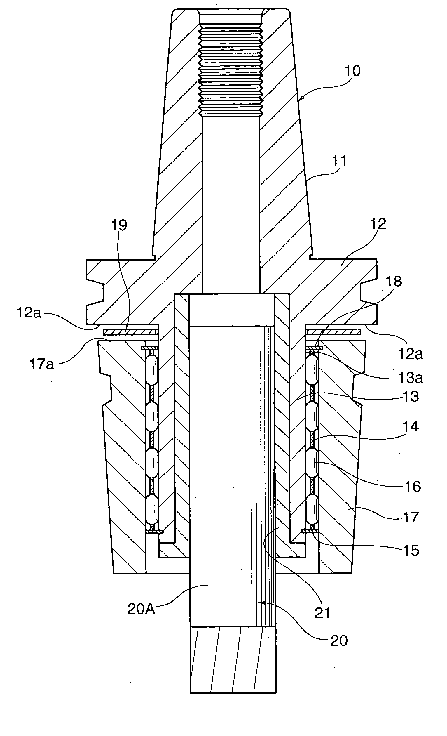
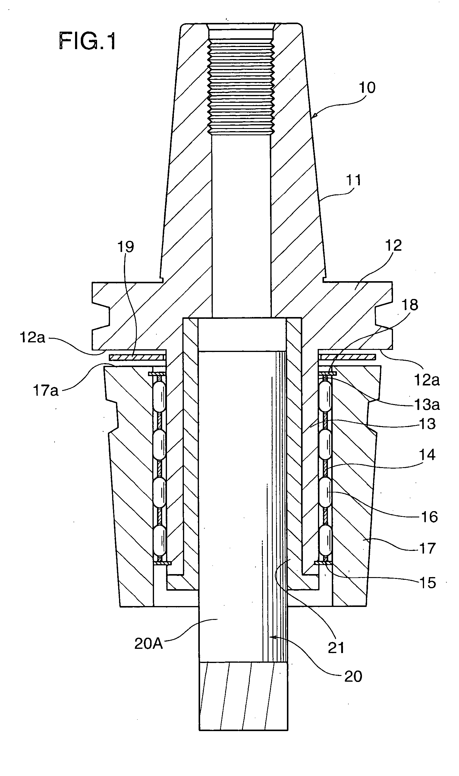
[0038]FIG. 1 shows a cross-sectional view of a chuck according to a first embodiment of the present invention.

[0039] As shown in FIG. 1, the tool chuck has a holder body 10, which has a tapered shank portion 11 to be inserted into a spindle of an unillustrated machine tool, a gripping flange 12 formed at the larger-diameter end of the tapered shank portion 11, and a chuck sleeve 13 that extends from an end surface 12a of the flange 12 opposite the tapered shank portion 11. The chuck sleeve 13 extends in the direction away from the tapered shank portion 11 such that the axis of the chuck sleeve 13 coincides with the axis of the tapered shank portion 11. The chuck sleeve 13 has a tapered outer circumferential surface 13a whose diameter decreases from the bottom end adjacent to the flange 12 toward the tip end.

[0040] Reference numeral 14 denotes a roller-retaining sleeve fitted onto the outer circumference of the chuck sleeve 13 with a clearance therebetween. The diameter of the roll...

second embodiment

[0047] Next, a chuck according to a second embodiment of the present invention will be described.

[0048] The chuck of the second embodiment shown in FIG. 4 is identical with that of the first embodiment, except that in the end surface 12a of the flange 12 opposite the tapered shank portion, a groove 22 having a predetermined depth (approximately 2 to 5 mm) is formed, at the bottom portion of the chuck sleeve 13 through which the chuck sleeve 13 is joined with the flange 12, such that the groove 22 extends along the outer circumference of the chuck sleeve 13 to form a ring-like shape. The ring-shaped, groove 22 allows the chuck sleeve 13 to be extended toward the flange 12 side without changing the tool length L1 of the holder body 10.

[0049] By virtue of the above-described structure, the radially inward elastic deformation of the chuck sleeve 13 in a bottom end area adjacent to the flange 12 is made substantially equal to that in the remaining area of the chuck sleeve 13.

[0050] Si...

third embodiment

[0053] Next, a chuck according to a third embodiment of the present invention will be described with reference to FIGS. 6 to 8.

[0054] In FIG. 6, structural elements identical with those shown in FIGS. 1 to 5 are denoted by the same reference numerals, and their repeated descriptions are omitted. Only portions different from those shown in FIGS. 1 to 5 will be mainly described.

[0055] The feature of the chuck according to the third embodiment resides in that the annular groove 22 is formed in the end surface of the flange 12 in order to increase the effective length of the chuck sleeve 13, and that a thrust-member holder 23 is provided in order to prevent play or movement of the thrust member 19 along the axial direction.

[0056] In the chuck of the third embodiment, the thrust-member holder 23 is fitted into the central opening of the thrust member 19. The thrust-member holder 23 has an opening for allowing passage of the chuck sleeve 13 therethrough, and a stepped portion 23a which...


PUM


Abstract

A chuck includes a holder body, a clamp sleeve, and a large number of needle rollers. The holder body has a shank portion, a flange, and a chuck sleeve. The clamp sleeve is fitted onto the outer circumference of the chuck sleeve such that the clamp sleeve is rotatable and axially movable relative to the chuck sleeve. The needle rollers are disposed between the chuck sleeve and the clamp sleeve over the entire circumference. The clamp sleeve is rotated to cause the needle rollers to revolve spirally along the outer circumferential surface of the chuck sleeve while rotating about their own axes in order to decrease and restore the diameter of the chuck sleeve. A thrust member is disposed between the end surface of the flange opposite the shank portion and a corresponding end surface of the clamp sleeve.

Description

BACKGROUND OF THE INVENTION [0001] 1. Field of the Invention [0002] The present invention relates to a chuck for chucking a cutting tool such as a drill or end mill, and more particularly to a chuck in which a clamp sleeve is fitted onto the outer circumference of a chuck sleeve of a holder body via needle rollers, and in which, through rotation of the clamp sleeve in a clamping direction, the diameter of the chuck sleeve is reduced in order to tightly chuck a desired tool. [0003] 2. Description of the Related Art [0004] A conventional chuck will be described with reference to FIG. 12. FIG. 12 is a cross-sectional view of a conventional tool chuck. [0005] As shown in FIG. 12, the tool chuck has a holder body 1. The tool holder body 1 has a tapered shank portion 1A to be inserted into a spindle of an unillustrated machine tool, a gripping flange 1B formed at the larger-diameter end of the tapered shank portion 1A, and a chuck sleeve 1C that extends from the end surface of the flange ...

Claims


Application Information

Patent Timeline
Patent Type & Authority Applications(United States)
IPC IPC(8): B23B31/117
CPCB23B31/117B23B2231/14Y10T279/17957Y10T279/17Y10T279/17965Y10S279/903
Inventor MATSUMOTO, MASAKAZUTAGUCHI, MASAHIROYAMAMOTO, YUSAKU
Owner NIKKEN KOSAKUSHO WORKS LTD
Why Eureka
Try Eureka