Volumetric shoulder for garments

a volumetric, shoulder technology, applied in the direction of overgarments, apparel, garments, etc., can solve the problems of loose jackets, upward movement of elasticized hems on lightweight jackets, and difficulty in adjusting the hem position

Inactive Publication Date: 2003-03-20
GREGG RON
View PDF0 Cites 69 Cited by
  • Summary
  • Abstract
  • Description
  • Claims
  • Application Information

AI Technical Summary

Problems solved by technology

Upward movement of a shirt hem due to raising of the arms can be problematic when the hem comes partially or completely untucked.
Upward movement of an elasticized hem on a lightweight jacket is problematic because the hem will not descend on its own when the arms are lowered, so the jacket is left loosely billowing in the way.
Furthermore, upward movement of a parka can be problematic when wearing a pack because parka fabric pulled up through the waist belt of the pack billows out in front when the arms are lowered.
Again, the functional results are virtually the same, and this technique cannot be used in cases where elastic materials are undesirable for various reasons, such as in a fully-taped waterproof parka or in a beautifully patterned shirt.
In fact, an exhaustive survey over the past 20 years has failed to discover any garment construction technique that allows the arms to be raised close to the vertical without substantial upward movement of an unrestrained hem.
Tightness can be uncomfortable, and, in extreme cases, can result in restricted motion and/or damage to the garment itself.
This is frequently acceptable, but there are many cases when it is less than desirable.
When garment weight is an issue, or the cost of the garment fabric is high, or when a well-fitted garment is desired for reasons of comfort, appearance, or functionality, it is less than desirable to simply make the garment oversized.
Again this is

Method used


Image

  • Volumetric shoulder for garments
  • Volumetric shoulder for garments
  • Volumetric shoulder for garments

Examples


Embodiment Construction

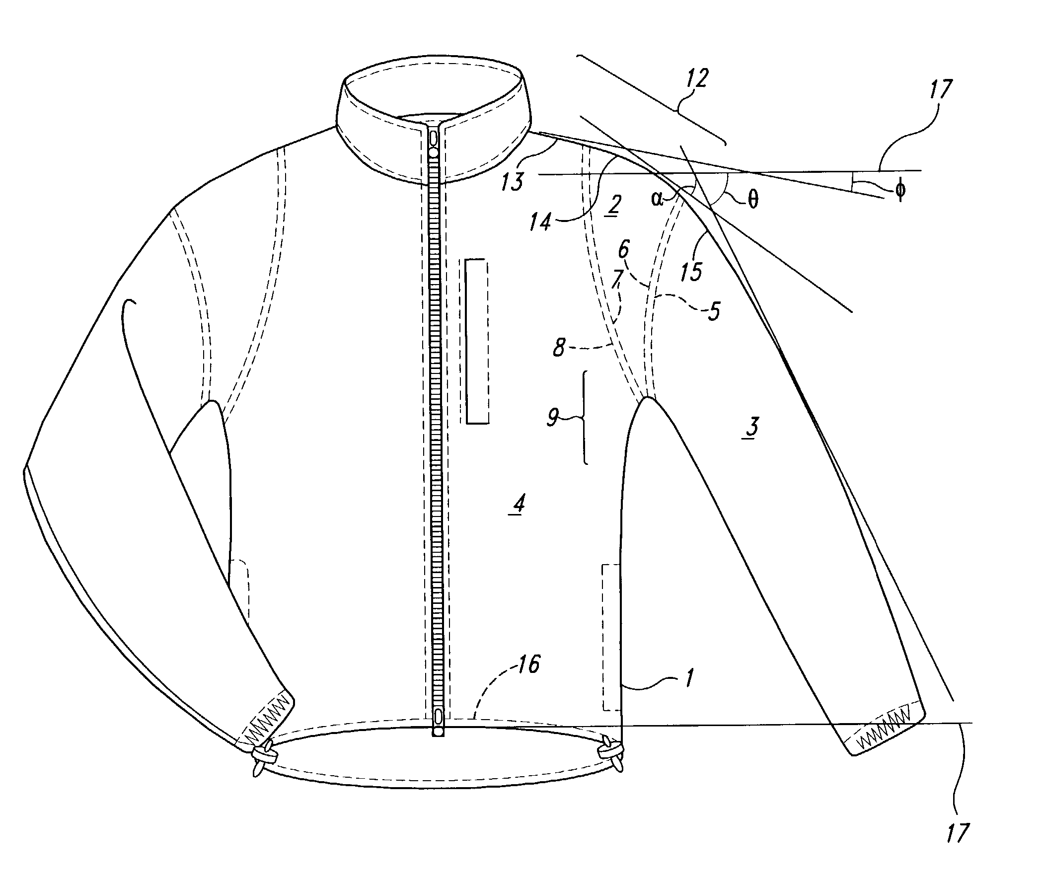
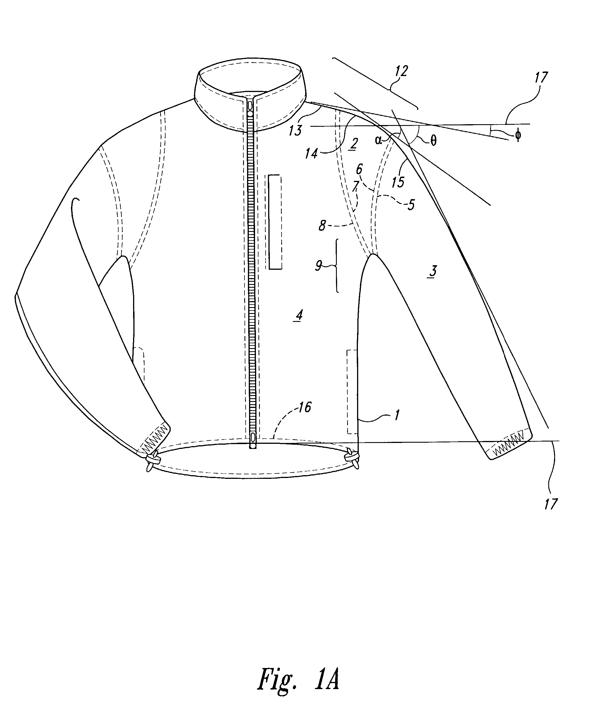
[0034] A first embodiment of the invention is illustrated in FIGS. 1A and 1B. FIG. 1A shows a front view of a jacket 1, with a separate section 2 interposed between a sleeve 3 and a jacket body 4. The separate section 2 wraps over a shoulder area 12, and it includes ends 10 and 11 that are joined together at a seam in an armpit area 9, typically by sewing or by fabric welding, although any other joining method is usable without affecting the utility of the invention. Joining of the ends 10, 11 of the separate section 2 in the armpit area 9 generally provides the best appearance and the best fabric utilization in manufacturing; however, it is entirely possible to break the separate section 2 anywhere else and join the ends together, such as on top of the shoulder area 12, for example.

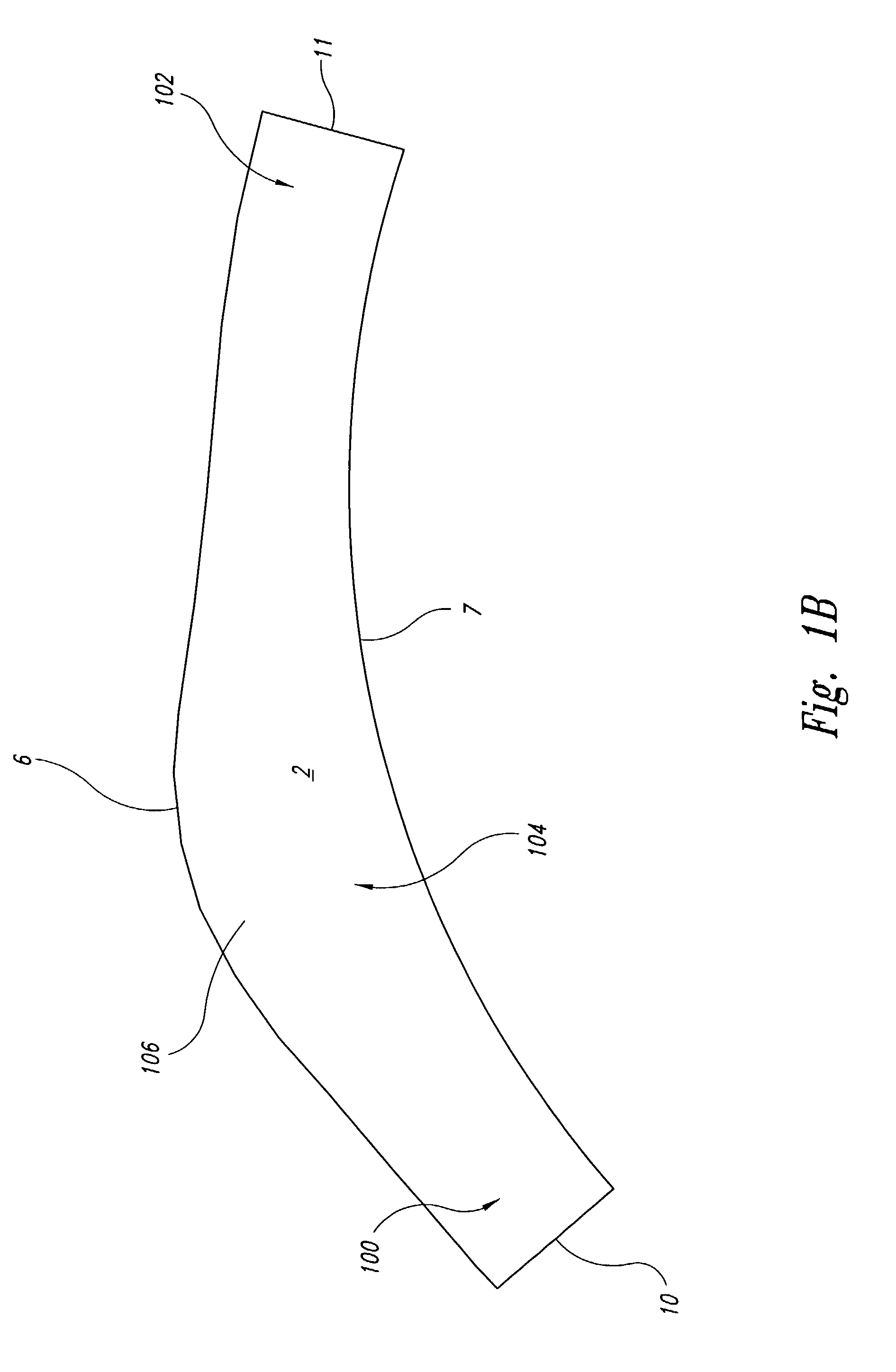
[0035] A typical pattern for the fabric used to make the separate section 2 is shown in FIG. 1B. The section 2 includes opposing longitudinal edges 6, 7 and opposing transverse edges 10, 11. The longitud...


PUM


Abstract

A separate section is introduced between the sleeve and the body of any garment such as a jacket, parka, wind shirt, or shirt of any type to isolate, to a considerable extent, the motion of the sleeve from the main body of the garment. This isolation of movement is accomplished by shaping the edges of the separate section and the adjoining edges of the garment body and the sleeve in such a way that excess fabric is available between the sleeve and the body of the garment regardless of which direction the arm is moved. In particular, excess fabric is available to accommodate the volume of the shoulder joint when it moves upward from a rest position as the arm is raised. The result is that the wearer can move the arm over a very wide range of motion with much less movement of the main body of the garment and much less movement of the sleeve cuff up and down the arm than with other methods of sleeve attachment.

Description

[0001] This application claims the benefit of U.S. Provisional Patent Application No. 60 / 311,372 filed Aug. 9, 2001, where this provisional application is incorporated herein by reference in its entirety.[0002] 1. Field of the Invention[0003] The present invention pertains to garment shoulder design, and more particularly, to a shoulder joint configuration for joining a sleeve to a garment body in which sleeve movement is isolated from the garment body.[0004] 2. Description of the Related Art[0005] It has long been desirable to provide shirts, jackets, parkas and the like with a construction in which movement of the body of the garment is minimized when the arms are raised. Upward movement of a shirt hem due to raising of the arms can be problematic when the hem comes partially or completely untucked. Upward movement of an elasticized hem on a lightweight jacket is problematic because the hem will not descend on its own when the arms are lowered, so the jacket is left loosely billow...

Claims


Application Information

Patent Timeline
IPC IPC(8): A41D27/10
CPCA41D27/10
Inventor GREGG, RON
Owner GREGG RON
Why Eureka
Try Eureka