Radio frequency patient identification and information system

a patient identification and information system technology, applied in the field of radio frequency patient identification and information system, can solve the problem that the latter will be swamped by the first respons

Inactive Publication Date: 2003-03-27
RICH MICHAEL JOHN
View PDF0 Cites 119 Cited by
  • Summary
  • Abstract
  • Description
  • Claims
  • Application Information

AI Technical Summary

Problems solved by technology

Thus, if both the interrogator and the transponder are operating on the sam

Method used


Image

  • Radio frequency patient identification and information system
  • Radio frequency patient identification and information system
  • Radio frequency patient identification and information system

Examples


first embodiment

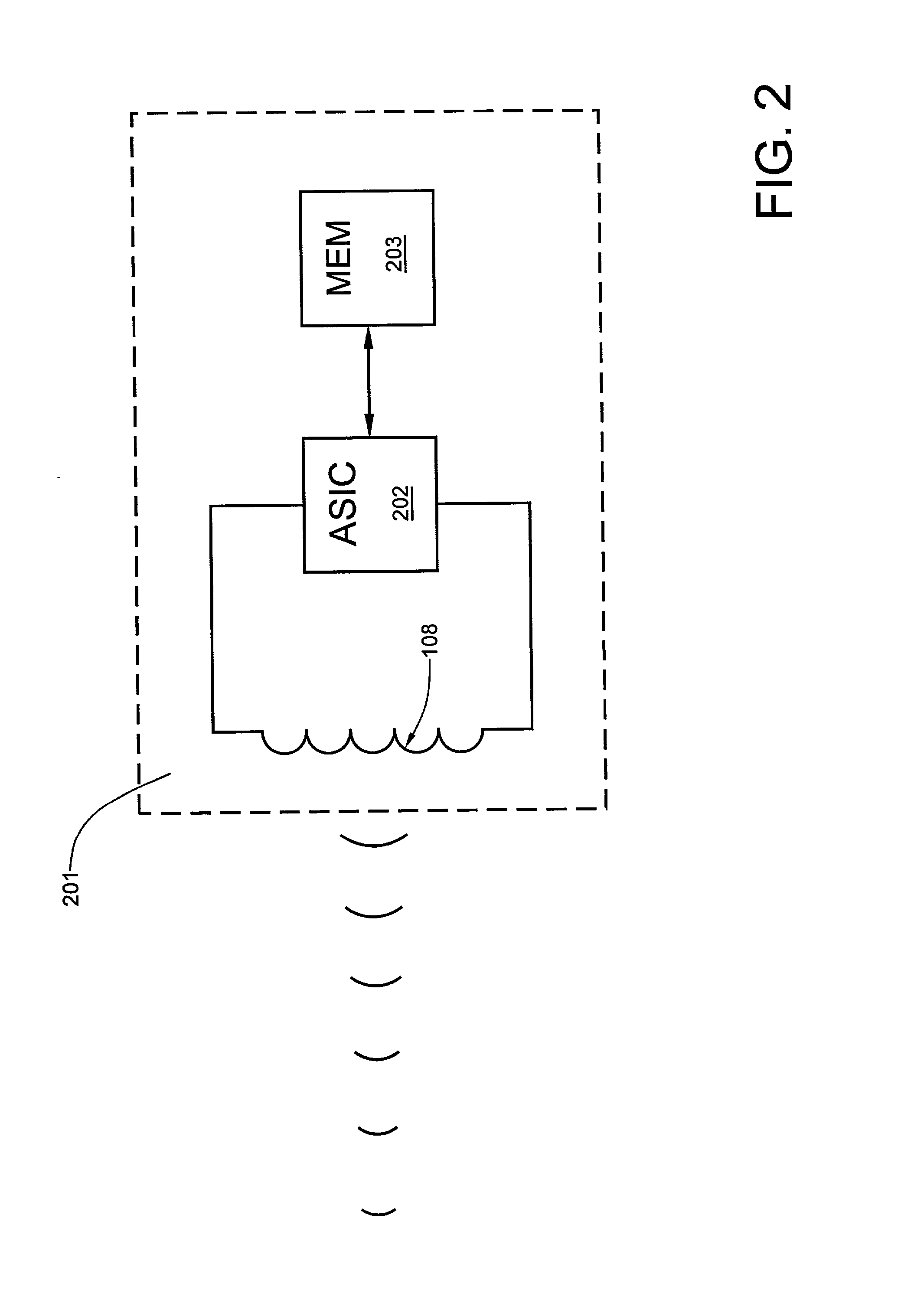
[0023] Referring now to FIG. 2, a first embodiment transponder 201 includes an application specific integrated circuit (ASIC) 202 that is bidirectionally coupled to a read / write memory 203. The ASIC 202 is also coupled to an antenna 108 that is used for both reception and transmission. In order to simplify the design and manufacture of the ASIC 202, a single frequency is employed for both reception and transmission. In order to prevent an individual's medical or other sensitive information from being accessed by unauthorized individuals, the transponder 201 may be stored in a foil envelope when access is not required.

second embodiment

[0024] Referring now to FIG. 3, a second embodiment transponder 301 is similar to that of FIG. 2, with the exception that a manually-operable receive and transmission enable switch 302 is placed in series with the antenna 108. Unless the switch 302 is in the closed-circuit position (shown by the dashed line), no reception or transmission is possible. Thus, the likelihood of an individual's medical or other sensitive information being accessed by an unauthorized individual is minimized.

third embodiment

[0025] Referring now to FIG. 4, a third embodiment transponder 401 incorporates a transmission enable switch 403 in the ASIC 402. Only transmission--not reception--may be disabled, as the ASIC must receive a security code from an interrogator that matches a programmed security code stored in a register of the ASIC. A security code match will result in the enable switch 403 being activated so that information from the memory 203 can be sent to the interrogator.

[0026] Referring now to FIG. 5, a transponder 501 is embedded beneath a patient's skinn 502 within a subcutaneous layer 503.

[0027] Referring now to FIG. 6, a transponder 602 is embedded in a credit card shaped and sized sheet of laminar polymeric plastic material.

[0028] Referring now to FIG. 7, a transponder 701 is incorporated in a watch-like device 700 designed to be worn about the wrist or ankle.

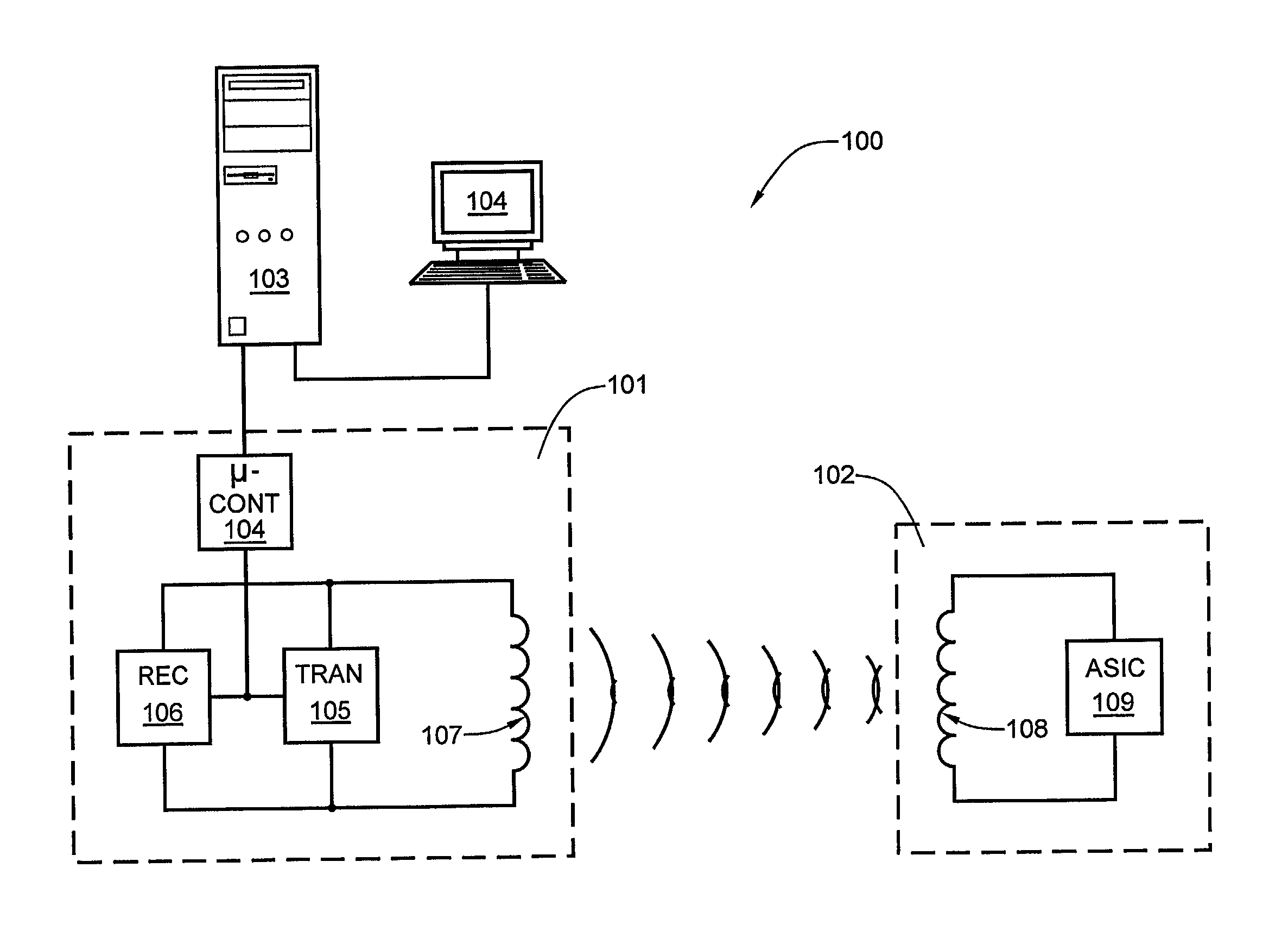
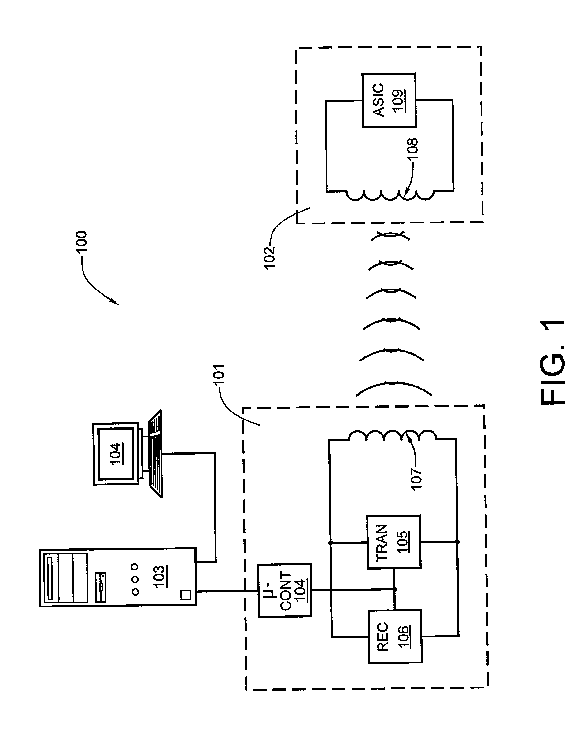
[0029] The interrogator used for the present invention may be of the type shown in FIG. 1, and it may be coupled to a computer 103 ...


PUM


Abstract

A radio frequency patient identification and information system includes a transponder which may be incorporated in a device which may be strapped to a patient's wrist or ankle, or hung around the patient's neck by a cord, carried as a card or label in the patient's purse or wallet, or embedded under the patient's skin. The transponder, in the form of an RFID tag, operates at a frequency standardized for this application, has a read/write memory of about at least two thousand bits-an amount sufficient to store information related to the patient's complete identification, such as home address, work address, next of kin, the patient's current primary care physicians, important contact telephone numbers, insurance information, complete medical history, all known allergies, and past and presently-prescribed medicines. The tag may be equipped with a transmission enable switch to prevent unauthorized access to the patient's medical history and other potentially sensitive information. An interrogator/reader/writer device is provided at each emergency health care facility and at the office of each health care provider.

Description

[0001] 1. Field of the Invention[0002] The present invention relates to medical alert bracelets and to radio frequency based transponders in general and, more particularly, to radio frequency identification tags having a read / write memory.[0003] 2. Description of the Prior Art[0004] Transponders were originally developed during World War II for use as IFF (Identify Friend or Foe) devices on aircraft so that they could be identified by radar operators. Only friendly aircraft were capable of providing a proper response to secret preprogrammed interrogation codes transmitted by an interrogator device.[0005] After the war, another important use for transponder-based, radio frequency identification (RFID) was implemented in the field of aviation. In response to an interrogator signal, an aircraft transponder returns an identification number (commonly called a "squawk code") and an encoded altitude value so that radar controllers can track the identity, the altitude and the location (dete...

Claims


Application Information

Patent Timeline
IPC IPC(8): G08B21/22
CPCG06F19/323G08B13/2462G08B21/22G16H10/65
Inventor RICH, MICHAEL JOHN
Owner RICH MICHAEL JOHN
Why Eureka
Try Eureka