Automatic brake system of motor vehicle

a technology of automatic brakes and motor vehicles, which is applied in the direction of braking systems, pedestrian/occupant safety arrangements, instruments, etc., can solve the problems that the automatic brake system of the publication has not shown a satisfied operation

Inactive Publication Date: 2003-04-10
NISSAN MOTOR CO LTD
View PDF1 Cites 52 Cited by
  • Summary
  • Abstract
  • Description
  • Claims
  • Application Information

AI Technical Summary

Benefits of technology

0008] More specifically, the present invention aims to provide an automatic brake system of a motor vehicle, w

Problems solved by technology

However, due to an inherent construction, the automatic brake syst

Method used


Image

  • Automatic brake system of motor vehicle
  • Automatic brake system of motor vehicle
  • Automatic brake system of motor vehicle

Examples


Embodiment Construction

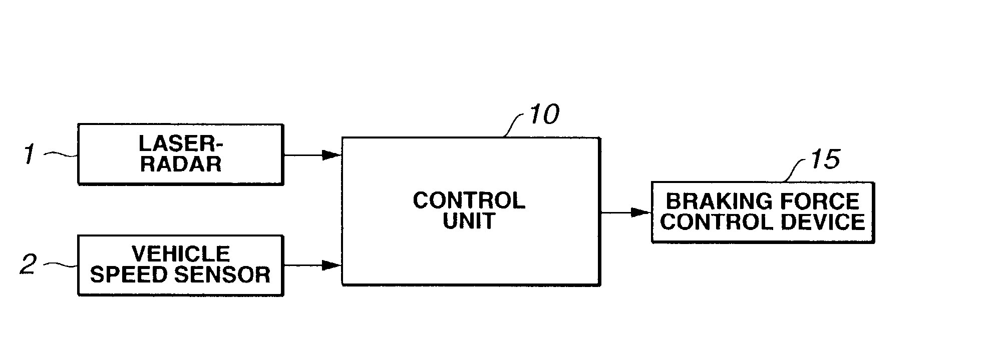
[0019] In FIG. 1, there is shown a block diagram of an automatic brake system of the present invention.

[0020] In the drawing, denoted by numeral 1 is a scanning type laser-radar that detects a vehicle interval distance, that is, the distance between an own vehicle and a preceding vehicle. It is to be noted that the own vehicle is the vehicle that has the automatic brake system of the invention mounted thereon, and the preceding vehicle is the vehicle that is running ahead of the own vehicle.

[0021] Laser-radar 1 is mounted on a laterally middle front position of the own vehicle. Laser-radar 1 emits periodically a laser ray forward scanning over a predetermined angle range and receives a laser ray that has been reflected from the preceding vehicle. Based on a time difference between the laser ray emitting timing and laser ray receiving timing, a vehicle interval distance between the preceding vehicle and the own vehicle is actually measured in each scanning angle. Denoted by numeral 2...


PUM


Abstract

When it is judged that a possible collision of the own vehicle with a preceding vehicle is avoidable by operation of either one of the brake pedal and steering wheel, a first grade braking force is automatically produced. While, when it is judged that the possible collision is unavoidable by operation of either of the brake pedal and steering wheel, a second grade braking force is automatically produced, which is greater than the first grade braking force.

Description

BACKGROUND OF INVENTION[0001] 1. Field of Invention[0002] The present invention relates in general to brake systems of wheeled motor vehicles, and more particularly the brake systems of an automatic type that automatically brakes the own vehicle when a collision against the preceding vehicle is highly estimated.[0003] 2. Description of Related Art[0004] Hitherto, for the purpose of safety driving, various automatic brake systems of the above-mentioned type have been proposed and put into practical use in the field of wheeled motor vehicles.[0005] Some of the automatic brake systems are of a type that includes a radar device mounted on the own vehicle for detecting a vehicle interval distance between the own vehicle and the preceding vehicle and automatically brakes the own vehicle when a collision against the preceding vehicle is highly estimated with respect to the detected vehicle interval distance and speeds of the two vehicles.[0006] Laid-open Japanese Patent Applications (Tokka...

Claims


Application Information

Patent Timeline
IPC IPC(8): B60R21/00B60T7/12B60T7/22B60T13/66B60W30/09B60W50/14G08G1/16
CPCB60T7/22B60T13/662G08G1/16B60W2050/143B60W30/09G08G1/166
Inventor SETO, YOJIYAMAMURA, YOSHINORIKOBAYASHI, YOSUKETAMURA, MINORU
Owner NISSAN MOTOR CO LTD
Why Eureka
Try Eureka