Two stage method

a technology of lithography and two stages, applied in the field of lithography instruments, can solve the problems of complexity creating time requirements of its own, distortion of the reticle, and distortion of the image focused on the substra

Inactive Publication Date: 2003-04-24
NIKON CORP
View PDF0 Cites 103 Cited by
  • Summary
  • Abstract
  • Description
  • Claims
  • Application Information

AI Technical Summary

Benefits of technology

0011] The present invention provides a two stage method where stage position may be determined using interferometers and one or more encoders. The stage assembly includes a plurality of interferometers mounted on a base for determining stage positions and encoders where interferometers are not feasible. The two stages move between multiple positions on the base and have mirrors affixed to them that cooperate with the other interferometer components to provide position data

Problems solved by technology

This complexity creates time requirements of its own.
This motion can generate dynamic reaction forces where the reticle is supported, leading to distortion of the reticle and, hence, distortion of the image focused on the substrate.
Lithography processes typically occur in a clean room/vacuum environment; this is a source of further complexity and also an

Method used


Image

  • Two stage method
  • Two stage method
  • Two stage method

Examples


Embodiment Construction

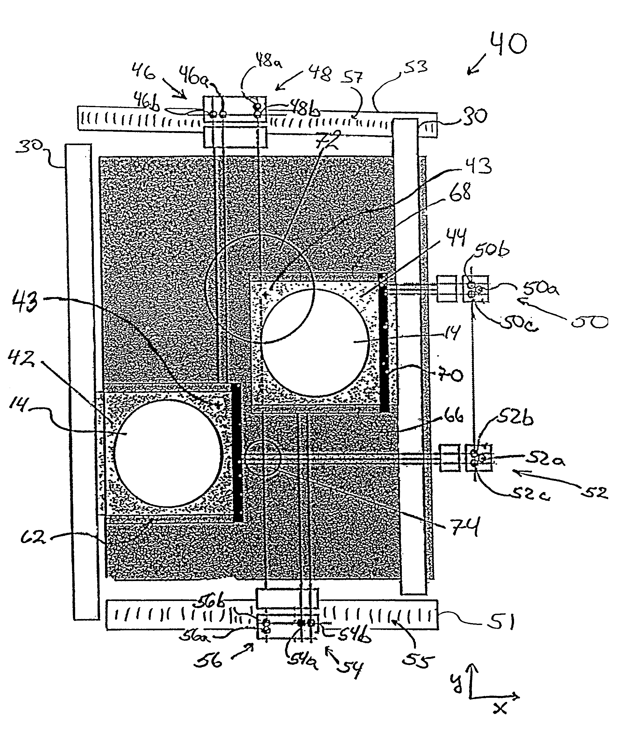
[0020] Referring now to FIG. 3, in which dual wafer stage assembly 40 is illustrated from above according to a preferred embodiment of the invention. Two wafer stage assembly 40 provides the capability for the system to rely on interferometers 46, 48, 50, 52, 54, 56 and encoders 55 and 57 to determine the position of wafer stages 42 and 44 during processing. Dual wafer stage assembly 40 generally comprises a first wafer stage 42, a second wafer stage 44, a base 60, and the interferometers and encoders mentioned above. Each interferometer cooperates with a reflective surface (mirror) 58, 62, 64, 66, 68, and 70 mounted on stages 42 and 44 so that they reflect back to the intended interferometers. Elements of base 60 necessary for the support, positioning, and movement of wafer stages 42 and 44 are illustrated as support elements 30 in FIG. 3 for purposes of clarity, but, as one of skill in the art would recognize, these functions may be accomplished by the shaft-type linear motors 51 ...


PUM


Abstract

This invention relates to a method for positioning two stages during semiconductor wafer processing. More particularly, the invention facilitates the use of two stages to improve system throughput by decreasing the rest-time of certain system components. While a typical single-stage apparatus requires that each step in the process be performed serially, this invention allows an amount of parallel processing with each stage at different steps of the process, and thus improves system throughput.

Description

FIELD OF THE INVENTION[0001] The invention relates to lithography instruments used for patterning and processing substrates such as semiconductor chips and wafers. More specifically, the invention is concerned with a method for positioning stages during the processing of the substrates affixed to those stages.BACKGROUND OF THE INVENTION[0002] In lithography processes the image from a reticle is transferred to a substrate, typically a wafer. System throughput is dependent upon the speeds of many separate steps that are performed in series. Throughput is therefore dependent on the duration of each step, which can include: loading, field image alignment, global alignment, and exposure.[0003] The production of an acceptable final product requires the complex interaction of the systems necessary to implement each step. This complexity creates time requirements of its own. For example, when exposing patterns on wafers and other substrates, the reticle is moved at high speeds between discr...

Claims


Application Information

Patent Timeline
IPC IPC(8): G03B27/42G03F7/20
CPCG03B27/42G03F7/70733G03F7/70716
Inventor INOUE, FUYUHIKO
Owner NIKON CORP
Why Eureka
Try Eureka