Loudspeaker damper and loudspeaker
- Summary
- Abstract
- Description
- Claims
- Application Information
AI Technical Summary
Problems solved by technology
Method used
Image

Examples
embodiment 2
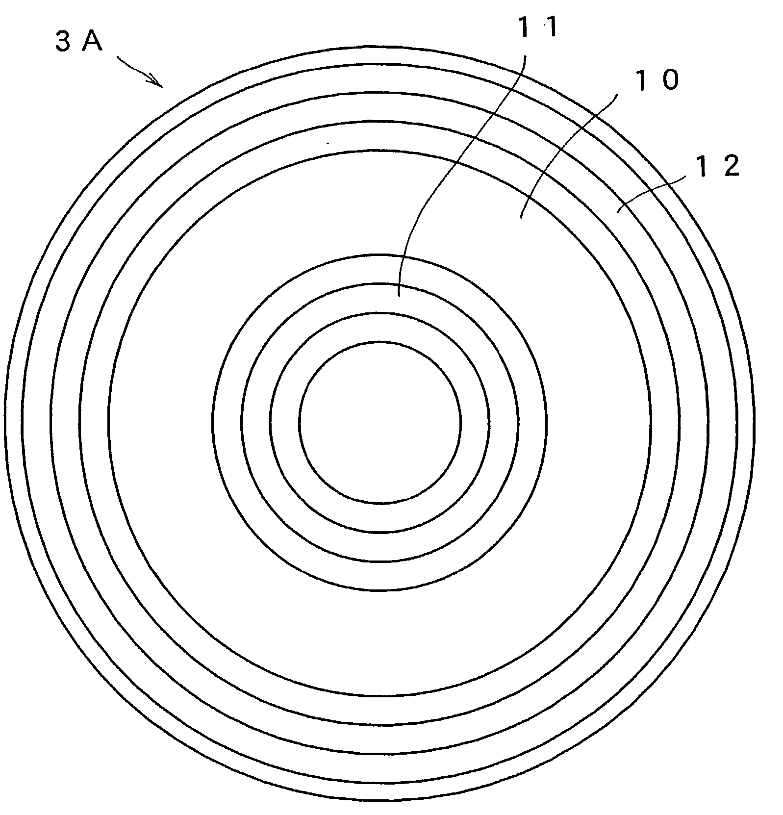
[0060] Embodiment 2
[0061] Next, a damper according to Embodiment 2 of the present invention will be described. FIG. 10 is a plan view showing a structure of damper of Embodiment 2. FIG. 11 is a cross-sectional view taken along line O-P shown in FIG. 10. FIG. 12 is a cross-sectional view taken along line O-Q shown in FIG. 10. The damper 3B is configured by an annular member with elliptic outline. As in Embodiment 1, complete round shaped opening is formed at an inner peripheral portion of the damper 3B such that the voice coil bobbin 1 is attached thereto. The damper 3B includes a flat portion 10A with elliptic outer peripheral profile, an outer peripheral waveform portion 12A with elliptic outer peripheral and inner peripheral profiles and an inner peripheral waveform portion 11A whose outer peripheral profile fits the flat portion 10A. As shown in FIG. 10, a direction of short axis of the damper is indicated by S and a direction of long axis of the damper is indicated by L. As seen...
embodiment 3
[0064] Embodiment 3
[0065] Next, a damper according to Embodiment 3 of the present invention will be described. FIG. 16 is a cross-sectional view showing a structure of damper according to Embodiment 3. The damper 3D includes a flat portion 10C, an inner peripheral waveform portion 11C and an outer peripheral waveform portion 12C. An inner connecting portion 13 is formed at a boundary portion between the flat portion 10C and the inner peripheral waveform portion 11C. An outer connecting portion 14 is formed at a boundary portion between the flat portion 10C and the outer peripheral waveform portion 12C. A reference letter Z shown in FIG. 16 indicates a direction that a voice coil vibrates in a case of using the damper 3D for a loudspeaker. A reference letter R indicates a radial direction of the damper 3D.
[0066] The inner connecting portion 13 is configured by an annular waveform having a height (depth) equal to or lower than a groove height (or a groove depth) of a concave or a conv...
embodiment 4
[0070] Embodiment 4
[0071] Next, a damper according to Embodiment 4 of the present invention will be described. FIG. 17 is a plan view showing a structure of damper of Embodiment 4. FIG. 18 is a cross-sectional view taken along line O-P shown in FIG. 17. The damper 3E includes a flat portion 10D, an inner peripheral waveform portion 11D and an outer peripheral waveform portion 12D. A large number of protruding portions 15 are provided at the flat portion 10D. In accordance with Embodiment 4, the protruding portions 15 are formed in a hemispherical shape. Diameters of the protruding portions 15 and their positions are random. A reference letter Z shown in FIG. 18 indicates a direction that a voice coil vibrates when the damper 3E is assembled into a loudspeaker. A reference letter R indicates a radial direction of the damper.
[0072] Effects of the damper with such structure will be described. By providing the flat portion 10D, the damper 3E hardly expands and contracts in the R directi...
PUM
 Abstract
Description
Claims
Application Information
 - R&D Engineer
- R&D Manager
- IP Professional
- Industry Leading Data Capabilities
- Powerful AI technology
- Patent DNA Extraction
Browse by: Latest US Patents, China's latest patents, Technical Efficacy Thesaurus, Application Domain, Technology Topic.
© 2024 PatSnap. All rights reserved.Legal|Privacy policy|Modern Slavery Act Transparency Statement|Sitemap