Assembly structure of super-high door

a super-high door and assembly structure technology, applied in the direction of building components, constructions, building constructions, etc., can solve the problems of deformation affecting application and safety, and achieve the effect of improving assembly structure, super-high door firmness, and strengthening assembly structur

Inactive Publication Date: 2003-05-08
NANYA PLASTICS CORP
View PDF0 Cites 21 Cited by
  • Summary
  • Abstract
  • Description
  • Claims
  • Application Information

AI Technical Summary

Benefits of technology

0005] The main purpose of this invention is to reinforce the assembly structure of a super-high door to prevent the super-high door from bending and deforming, by inlaying an U-shape reinforcing iron of which the

Problems solved by technology

In general the assembly structure of the super-high door is not strong enough to support the weight of its

Method used


Image

  • Assembly structure of super-high door
  • Assembly structure of super-high door
  • Assembly structure of super-high door

Examples


Embodiment Construction

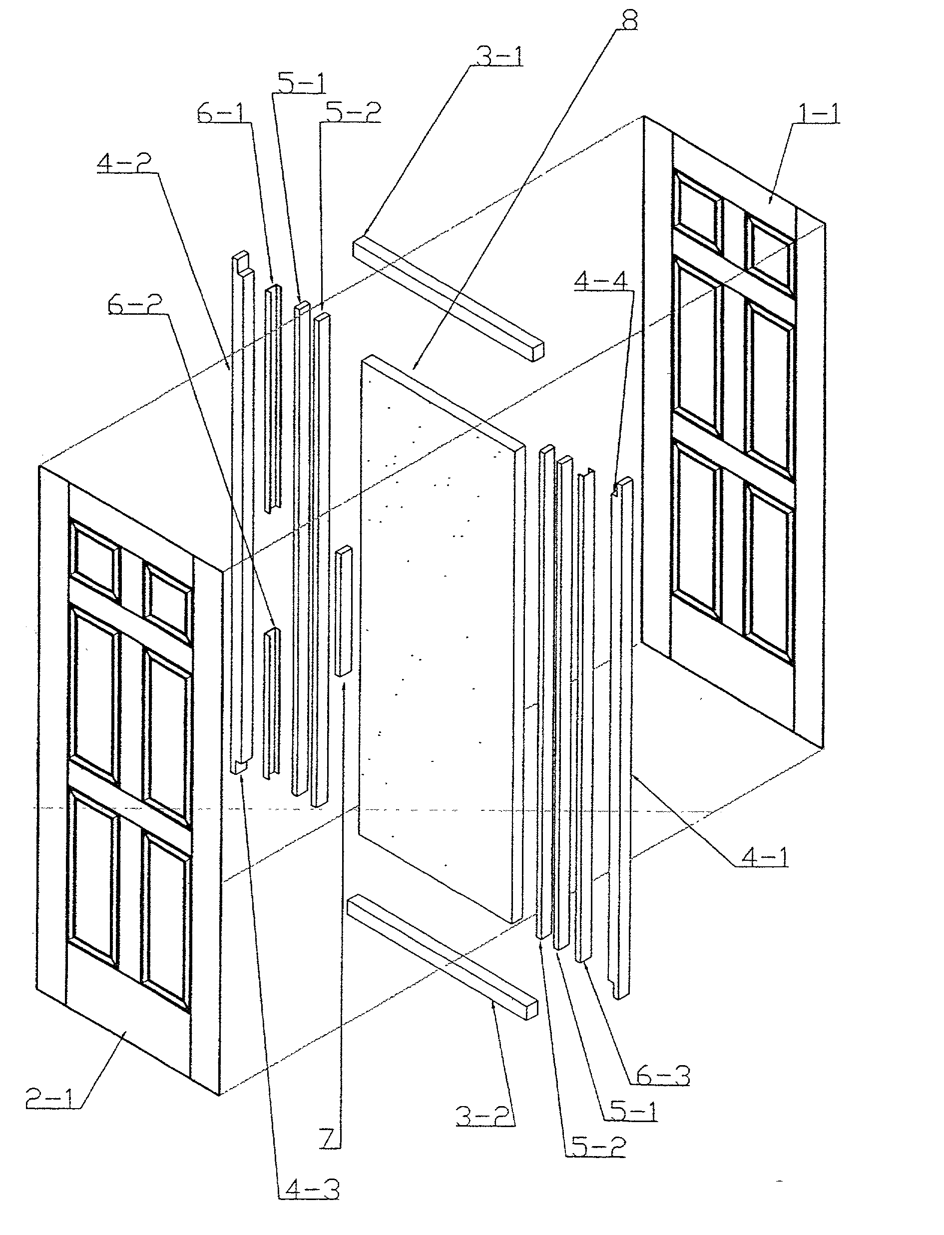
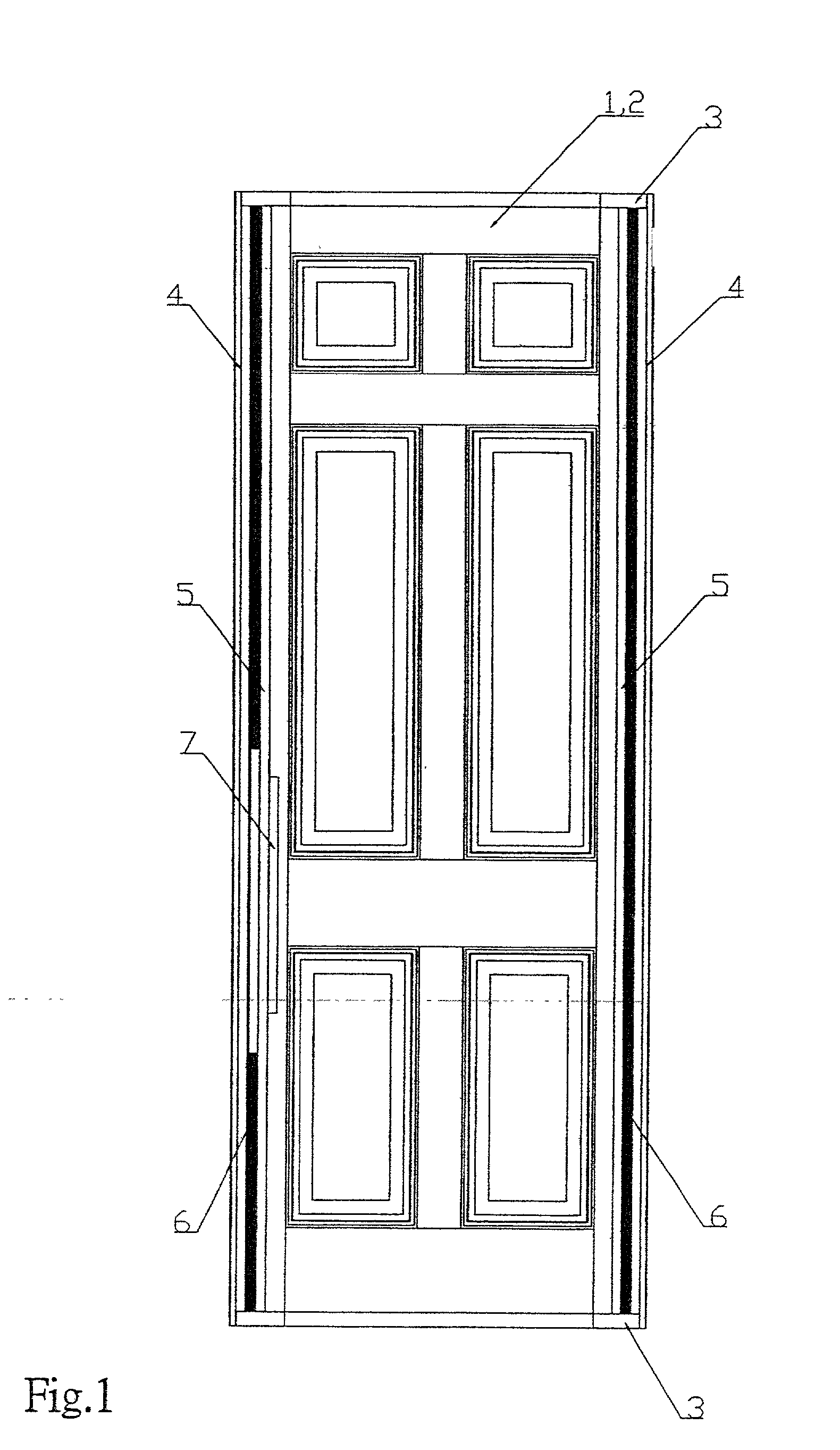
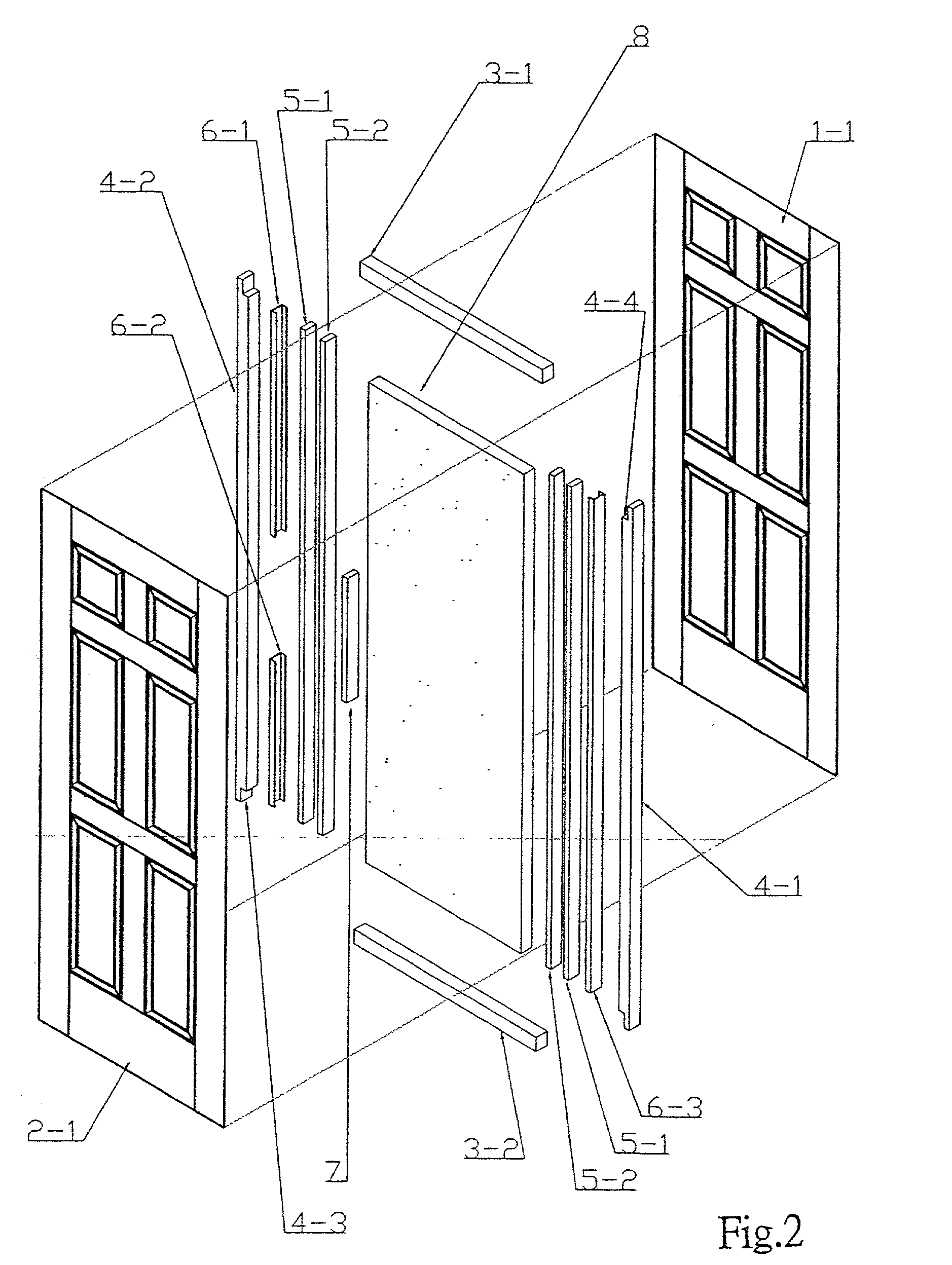
[0034] This invention improves the assembly structure of the conventional super-high door by installing multiple reinforcing structures such as the U-shape reinforcing iron and the wood strip so as to have the advantage of preventing the door from bending and deforming caused by its height too high. To help be clearly understood, the essence of the skill of this invention in combination of drawings is described in detail as follows:

[0035] Referring to FIG. 1 and FIG. 2, the assembly structure of the super-high door of this invention comprises two hubbed door skins 1 or 2, a top edge-sealing angle bar 3-1, a bottom edge-sealing angle bar 3-2, a left edge-sealing angle bar 4-2, a right edge-sealing angle bar 4-1, a couple of left and right wood strips 5-1, another couple of left and right wood strips 5-2, a left longer U-shape reinforcing iron 6-1, a left shorter U-shape reinforcing iron 6-2, a right U-shape reinforcing iron 6-3, and a handle area reinforcing angle bar 7.

[0036] The th...


PUM


Abstract

The assembly structure of the super-high door of this invention comprises members of two hubbed door skins, a top edge-sealing angle bar, a bottom edge-sealing angle bar, a left edge-sealing angle bar, and a right edge-sealing angle bar. Said hubbed door skins are integrally molded flush-edged structures which are positioned by the flange ribs of the left edge-sealing angle bar and the right edge-sealing angle bar; meanwhile, the top edge-sealing angle bar and the bottom edge-sealing angle bar are positioned by the milled notches at the top and the bottom ends of the left edge-sealing angle bar and the right edge-sealing angle bar. This invention is characterized in: the inner side of the upper longer region (above the handle) of the left edge-sealing angle bar and the inner side of the lower shorter region (below the handle) of the left edge-sealing angle bar are respectively inlaid with two U-shape reinforcing irons of which each length is corresponding to each length of said two regions, then a wood strip with a length a little bit shorter than that of the left edge-sealing angle bar is inserted into the inner of the two U-shape reinforcing irons having different length, then closely joined, by a nail gun and an adhesive, to another wood strip of which the handle position is inlaid with a reinforcing angle bar; besides, the inner side of the right edge-sealing angle bar is inlaid with an U-shape reinforcing iron of which the length is a little bit shorter than that of the right edge-sealing angle bar, then a wood strip with a length corresponding to that of the U-shape reinforcing iron is inserted thereto and closely joined, by a nail gun and adhesives, to another wood strip; thereafter, said structure is coated with an adhesive and press-assembled with two hubbed door skins; after assembling, the bottom edge-sealing angle bar is drilled a hole thereof and filled up with ammonium polyester foamed plastic to form a super-high door structure which will not bent nor deform.

Description

BACKGROUN OF THE PRESENT INVENTIION[0001] 1. Field of this invention[0002] This invention relates to an improvement on the assembly structure of a super-high door by installing multiple reinforcing structures such as the U-shape reinforcing iron and the wood strip to prevent the door from bending and deforming caused by its height too high.[0003] 2. Description of Prior Art[0004] Referring to the traditional doors in the market, there are roughly two kinds of door; one is the door with an ordinary height of about 200 cm (6 ft 8 in), the other one is the super-high door with a height of about 240 cm (8 ft). In general the assembly structure of the super-high door is not strong enough to support the weight of itself due to its height too high, which causes bending and deformation to affect its application and safety. Therefore, reinforcing the assembly structure of the super-high door is worthy of the endeavor of the industry to research and develop.SUMMARY OF THIS INVENTION[0005] The...

Claims


Application Information

Patent Timeline
IPC IPC(8): E06B3/70E06B3/82
CPCE06B3/7001E06B2003/7063E06B3/825
Inventor WANG CHEN, KUEI YUNG
Owner NANYA PLASTICS CORP
Why Eureka
Try Eureka