Eureka AIR delivers breakthrough ideas for toughest innovation challenges, trusted by R&D personnel around the world.

Echo attenuating method and device

a technology of attenuating method and attenuating device, which is applied in the direction of sound producing device, transmission, instruments, etc., can solve the problems of inconvenient operation of hand-free communication terminal, inconvenient use, and inability to interact with the communication terminal

Inactive Publication Date: 2003-06-05
FRANCE TELECOM SA
View PDF7 Cites 25 Cited by
  • Summary
  • Abstract
  • Description
  • Claims
  • Application Information

AI Technical Summary

Problems solved by technology

Acoustic echo is a major obstacle to proper operation of hand-free communications terminals.
Because of this constraint, the communications terminal is not very interactive and the user can have the feeling that the hands-free function does not work well.
The mechanical decoupling solution is effective in reducing coupling by vibration, but industrially speaking it is expensive.
Furthermore, when the playback system forms an integral portion of an assembly that also includes the sound pickup device, as is the case of a television monitor including loudspeakers and microphones or of a monitor having placed thereon a device that includes microphones, it is not possible to envisage isolating the loudspeakers from the shell of the assembly.
In practice, that technique does not give satisfaction the characteristics of the coupling change, even if only to a very small extent, for example due to the communications terminal being assembled and / or disassembled or due to a change in the characteristics of the microphones.
Furthermore, that technique is unsuitable if the disturbances are of a non linear nature, i.e. if the disturbances cannot be modelled by a convolution product between the signal coming from the loudspeaker and a filter impulse response.
Furthermore, the behavior of transducers is rarely linear, since they are generally subject to distortion and / or to saturation, both of which are typical examples of non-linear operation.
Finally, those limitations make the filter compensation technique relatively ineffective.
The effectiveness of those systems is highly sensitive to mismatches between the microphones or the acquisition channels.
Consequently, those systems require components to be sorted and microphones to be calibrated accurately, and such matching can become lost over time.
In addition, adding a display screen, a keypad, or a swivel-mounted camera can break the symmetry between the loudspeakers and the microphones.
Furthermore, when the number N of microphones exceeds two, such devices are not optimal since N degrees of freedom are available for satisfying two constraints, namely fixing gain in a given direction and cancelling direct coupling.
To obtain such a difference, it is necessary to position the microphones sufficiently close to the loudspeaker which gives rise to conditions that are very unfavorable in terms of coupling.
That puts a limit on passband and increases sensitivity to obstacles situated nearby.
When the sound source is situated in a noisy or reverberating environment, the directivity of a single sensor can be insufficient for extracting signal from noise.
This method provides good effectiveness at high frequencies, but at low frequencies (f<1000 Hz), the difficulty remains, for several reasons:
lack of directivity due to the small size of the antenna;
less robustness because of the high sensitivity at low frequencies to disparities between sensors, because of the effect of the TV screen, if any; and

Method used


Image

  • Echo attenuating method and device
  • Echo attenuating method and device
  • Echo attenuating method and device

Examples


Embodiment Construction

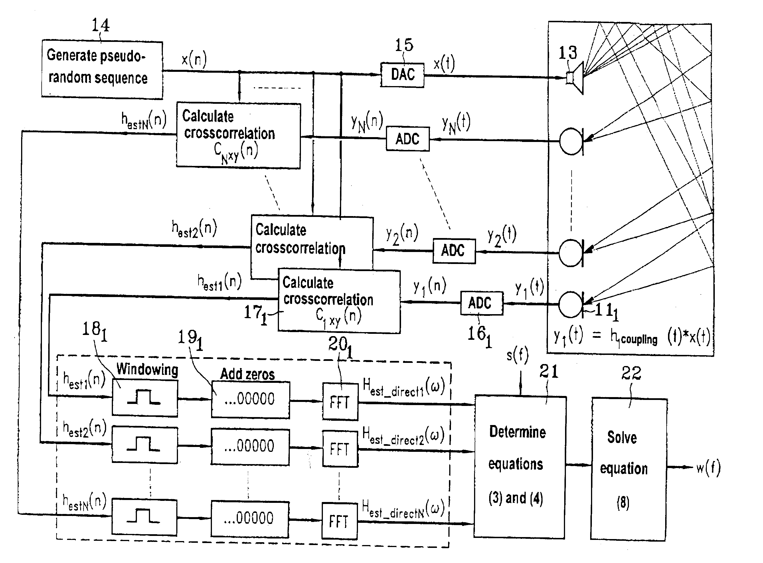
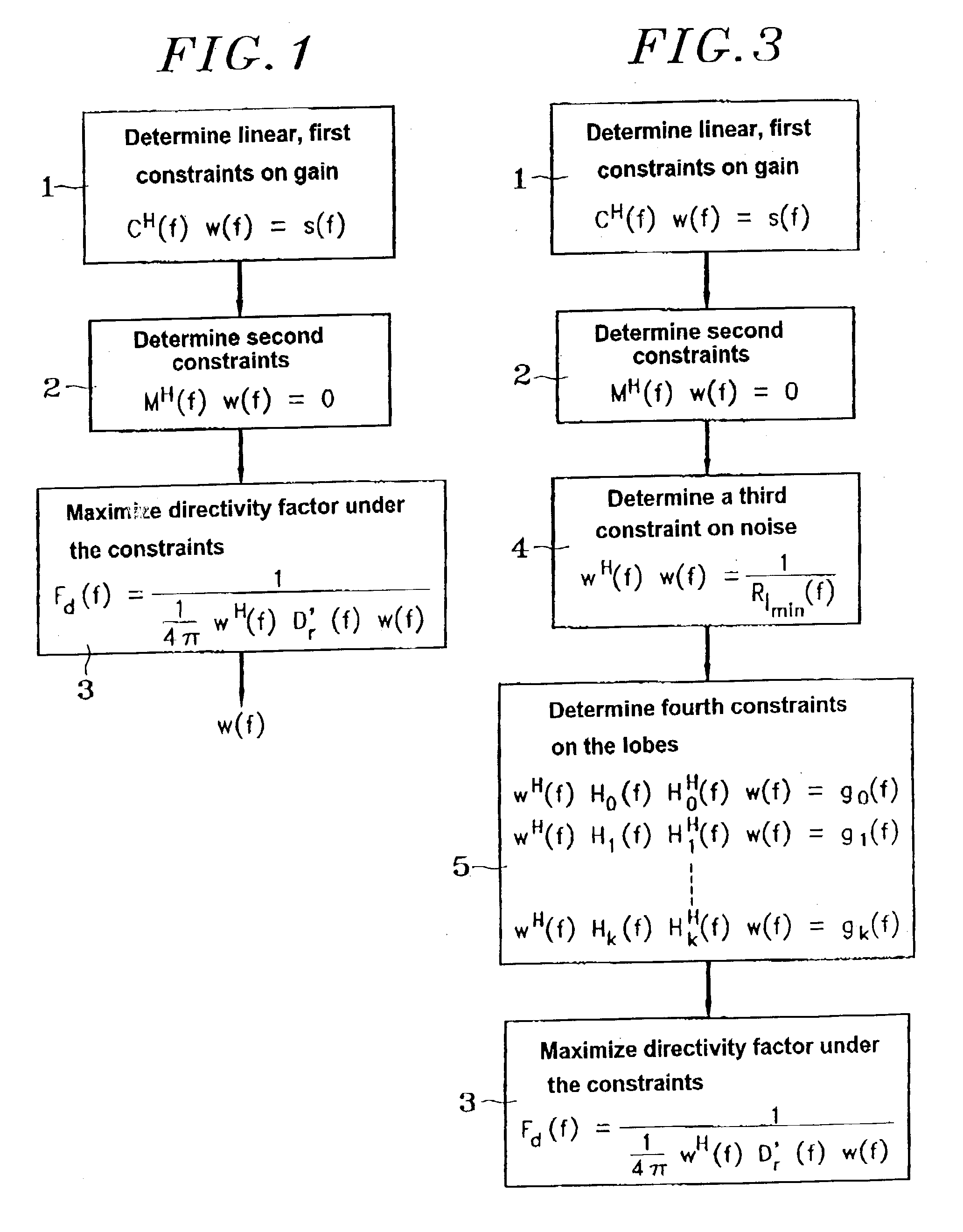
[0046] The echo reducing method of the invention is implemented with a multi-sensor sound pickup device forming an antenna and a sound playback device. The method of the invention consists in subjecting the output signals from the sensors of the sound pickup device to complex weights w(f), said weights being calculated by maximizing the directivity factor F.sub.d(f) under constraints at low frequencies and in the near field. The method takes place in several steps as described below and shown in FIG. 1.

[0047] In a first step 1, the method of the invention consists in determining the expression for the linear first constraint (3) of desired gain in the far field in directions corresponding to the useful sources (speakers), as defined by the matrix equation:

C.sup.H(f)w(f)=s(f) (3)

[0048] in which equation:

[0049] C(f) is the "constraint" matrix containing the theoretical propagation vectors calculated on the basis of a propagation model of the free field type or as measured under free f...


PUM


Abstract

The present invention relates to an echo reduction method implemented with a multi-sensor sound pickup device (8) forming an antenna (10), and a sound playback device (13). The method consists in subjecting the output signals ym(t) from the sensors (11m) to complex weights w(f), said weights w(f) being calculated by maximizing the directivity factor Fd(f) under constraints at low frequencies and in the near field. The invention also provides an echo reduction apparatus (6). The apparatus comprises: a multi-sensor sound pickup device (8) forming an antenna (10); means for calculating a first constraint; and means for calculating a second constraint.

Description

[0001] The invention relates to the field of acoustics in air and it applies in particular to systems for wiring halls and rooms for sound.[0002] The present invention relates to an echo reduction method implemented with a multi-sensor sound pickup device constituting an antenna and a sound playback device. The invention also relates to echo reduction apparatus designed to operate with a sound playback device to implement the method of the invention. The frequency domain to which the invention applies is the speech domain and more particularly that of low frequency speech signals.[0003] Description of the Prior Art[0004] A most advantageous application of the invention lies in reducing the echo in a sound pickup device in a teleconferencing system, thereby making so-called "hands-free" communication possible without needing to use an offset microphone.[0005] Acoustic echo is a major obstacle to proper operation of hand-free communications terminals. This acoustic echo is the result ...

Claims


Application Information

Patent Timeline
IPC IPC(8): G10K15/00H04R3/02H04M1/60H04M9/08
CPCH04M9/082
Inventor DEBAIL, BERNARD
Owner FRANCE TELECOM SA
Why Eureka
Eureka Blog
Learn More