Power line communication system

a technology of communication system and power line, applied in the direction of power distribution line transmission, frequency division multiplex, orthogonal multiplex, etc., can solve the problems of noise and inconsistent impedance, cost and time-consuming just to set up the network infrastructure, and the complexity and cost of the analog front end. , to achieve the effect of reducing cost, simplifying filtering design, and reducing complexity

Inactive Publication Date: 2003-07-17
ARKADOS
View PDF12 Cites 187 Cited by
  • Summary
  • Abstract
  • Description
  • Claims
  • Application Information

AI Technical Summary

Benefits of technology

The invention allows for the re-mapping of carriers in a multi-carrier system to another area of available frequency range, which makes certain frequency ranges available to another adjacent network while still using the existing system's bandwidth. The invention also addresses the main problem of designing an analog front end for a broadband communication system by increasing the sampling rate of the analog front end, which simplifies filtering designs and reduces complexity and cost.

Problems solved by technology

The technical problem of this patent text is not specified and requires further analysis and interpretation.

Method used


Image

  • Power line communication system
  • Power line communication system
  • Power line communication system

Examples


Embodiment Construction

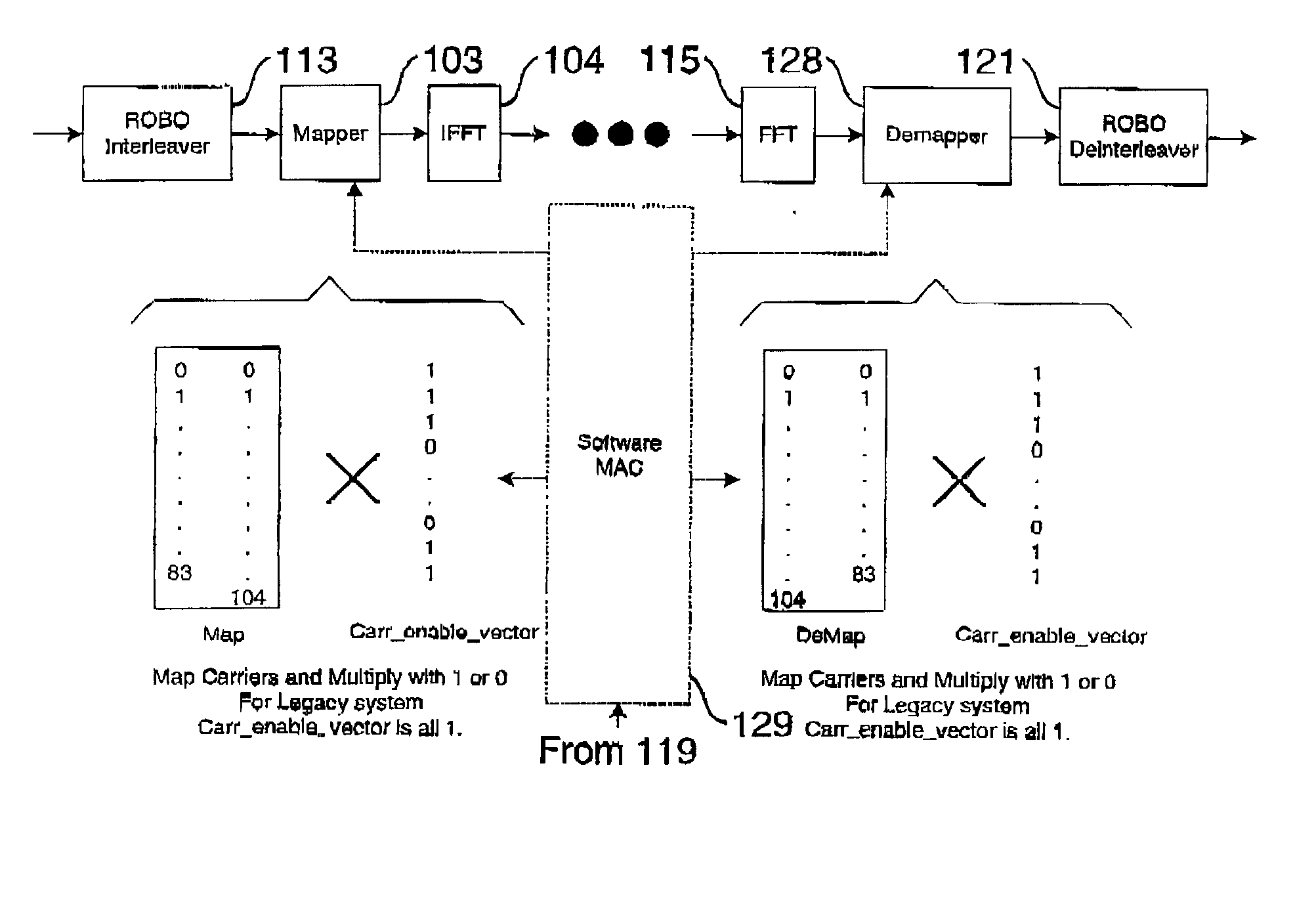
[0045] For a legacy system, a listing of the carrier numbers and frequencies are shown in Table 1.

2TABLE 1 HomePlug Carrier Frequencies Center Center Carrier Frequency Carrier Frequency Carrier Center Number MHz Number MHz Number Frequency 0 4.4921875 28 9.9609375 56 15.4296875 1 4.6875 29 10.15625 57 15.625 2 4.8828125 30 10.3515625 58 15.8203125 3 5.078125 31 10.546875 59 16.015625 4 5.2734375 32 10.7421875 60 16.2109375 5 5.46875 33 10.9375 61 16.40625 6 5.6640625 34 11.1328125 62 16.6015625 7 5.859375 35 11.328125 63 16.796875 8 6.0546875 36 11.5234375 64 16.9921875 9 6.25 37 11.71875 65 17.1875 10 6.4453125 38 11.9140625 66 17.3828125 11 6.640625 39 12.109375 87 17.578125 12 6.8359375 40 12.3046875 68 17.7734375 13 7.03125 41 12.5 69 17.96875 14 7.2265625 42 12.6953125 70 18.1640625 15 7.421875 43 12.890625 71 18.359375 16 7.6171875 44 13.0859375 72 18.5546875 17 7.8125 45 13.28125 73 18.75 18 8.0078125 46 13.4765625 74 18.9453125 19 8.203125 47 13.671875 75 19.140625 20 8.3984...


PUM


Abstract

Power line communication method and apparatus in which data modulated radio frequency carriers from two different sources are transmitted by the power line, the range of frequencies of the carriers from one source partially overlapping the range of frequencies of the carriers from the other source, and in which carriers of the one source are shifted to frequencies other than the overlapping frequencies when carriers at the overlapping frequencies and from the other source are present on the line. Optionally, the data signal sampling rate can be changed to simplify signal filtering requirements.

Description


Claims


Application Information

Patent Timeline
Owner ARKADOS
Why Eureka
Try Eureka