Eureka AIR delivers breakthrough ideas for toughest innovation challenges, trusted by R&D personnel around the world.

Telescopic stand for optical or photographic apparatus and the like

Inactive Publication Date: 2003-08-07
LINO MANFROTTO & CO SPA
View PDF13 Cites 2 Cited by
  • Summary
  • Abstract
  • Description
  • Claims
  • Application Information

AI Technical Summary

Benefits of technology

[0006] The technical problem underlying the invention is that of providing a telescopic stand, typically constructed in the form of a tripod, which is designed structurally and functionally to overcome all of the disadvantages discussed with reference to the prior art mentioned.

Problems solved by technology

A disadvantage of this device is that the spreader imposes a specific and predetermined relative positioning of the legs, limiting the versatility of use of the tripod.
However, this technical solution enables the three legs to be controlled simultaneously only by a complex manoeuvre to operate all of the locking devices on the legs at the same time.

Method used


Image

  • Telescopic stand for optical or photographic apparatus and the like
  • Telescopic stand for optical or photographic apparatus and the like
  • Telescopic stand for optical or photographic apparatus and the like

Examples


Embodiment Construction

[0006] The technical problem underlying the invention is that of providing a telescopic stand, typically constructed in the form of a tripod, which is designed structurally and functionally to overcome all of the disadvantages discussed with reference to the prior art mentioned.

[0007] This problem is solved by the invention by a telescopic stand formed in accordance with the appended claims.

[0008] The characteristics and the advantages of the invention will become clearer from the detailed description of a preferred but not exclusive embodiment thereof, given by way of non-limiting example with reference to the appended drawings, in which:

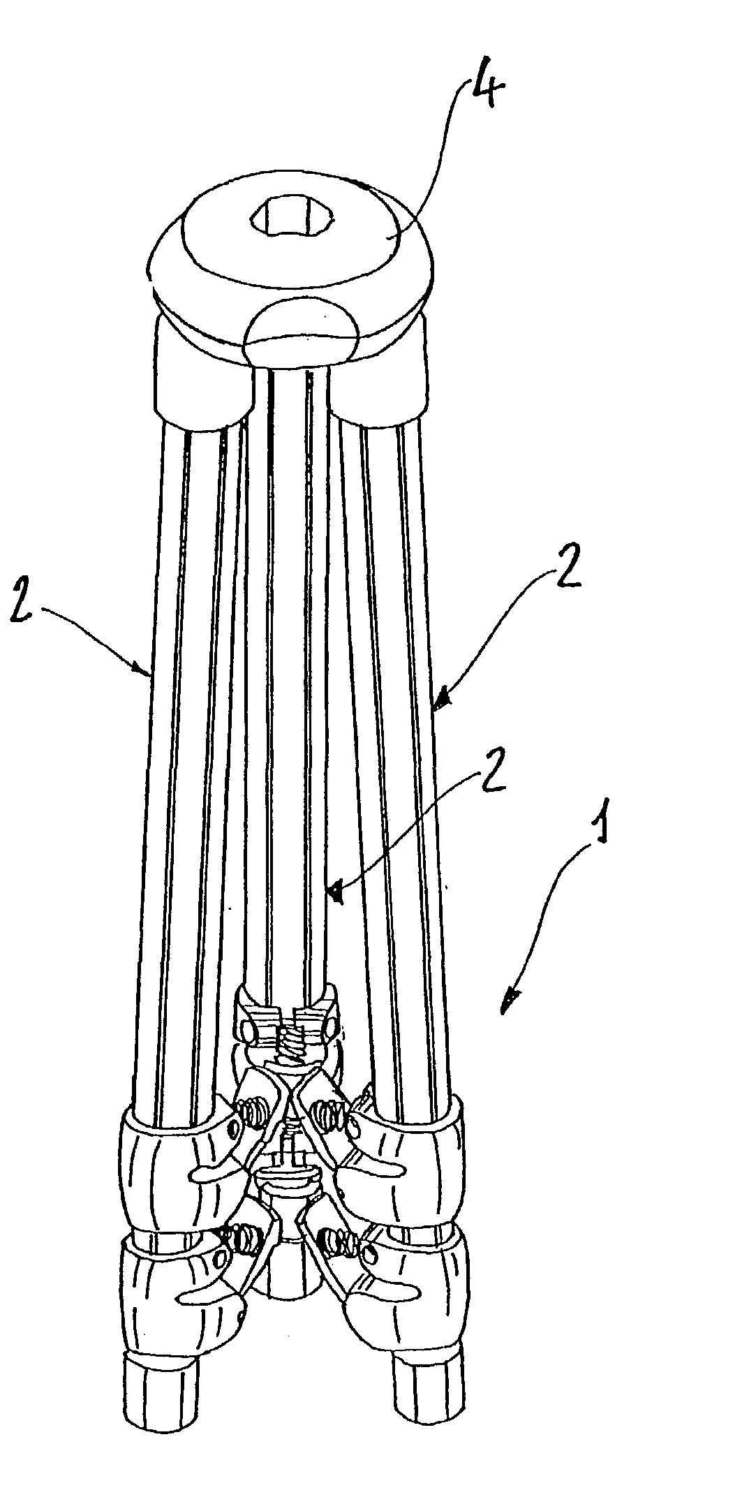
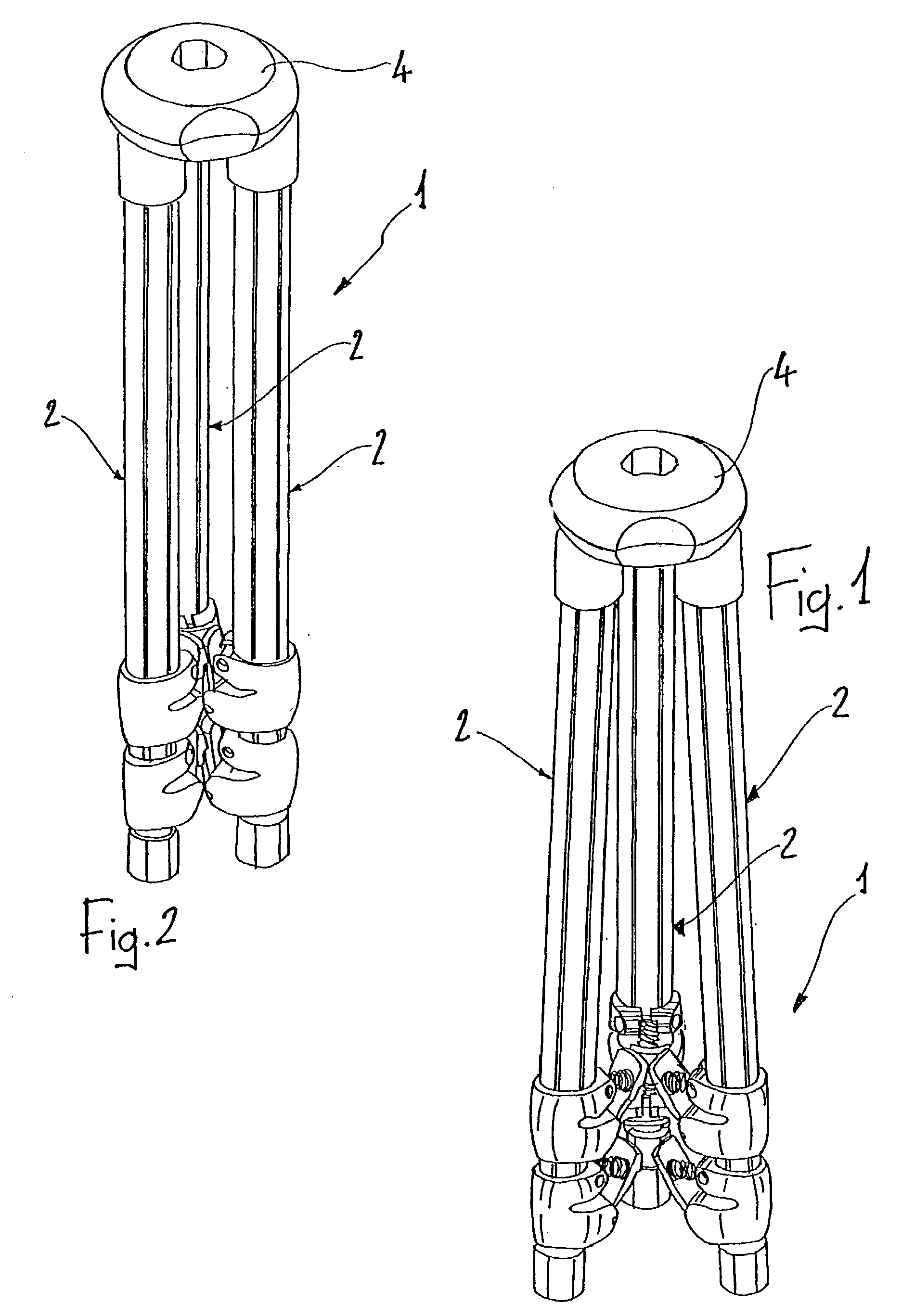
[0009] FIG. 1 is a perspective view of a photographic tripod according to the invention, in the semi-open position,

[0010] FIG. 2 is a perspective view of the tripod of FIG. 1, in the closed position,

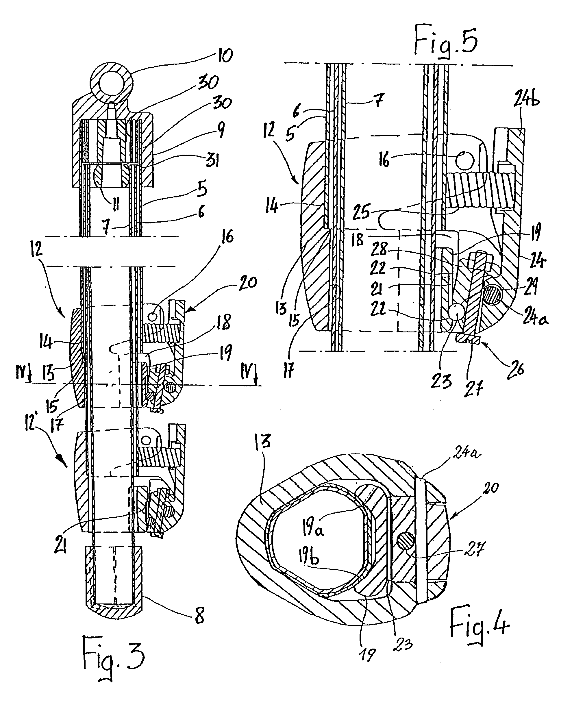
[0011] FIG. 3 is a longitudinal section through a leg of the tripod of the previous drawings,

[0012] FIG. 4 is a section taken on the line IV-IV of FIG....


PUM


Abstract

A telescopic stand is described and comprises at least two legs (2) and, for each leg, at least two elements (5, 6, 7) which are slidable telescopically relative to one another, locking means (12) on each leg (2), the locking means (12) being switchable between a locking condition and a release condition in which relative sliding between the elements of the respective leg (2) is prevented at least in one direction, or is unrestricted, respectively, and the locking means being switched to the release condition in at least one predetermined condition of relative positioning of the legs (2). The locking means comprises respective facing and opposed appendages (24b) which project towards one another from the respective legs (2) and, when pressed against one another, can interact with one another in the release condition when the legs (2) are gathered together.

Description

[0001] The subject of the present invention is a telescopic stand for optical or photographic apparatus and the like, according to the preamble to the main claim.TECHNOLOGICAL BACKGROUND[0002] In these stands, there is a need to facilitate initial and final positioning operations, enabling the legs to be extended quickly and simultaneously or, conversely, to be returned rapidly from the extended position to a fully retracted position.[0003] For this purpose, it is known to provide controls which enable the locking systems of the three legs to be controlled simultaneously. An example of this technology is described in U.S. Pat. No. 4,666,112. This document provides for each tripod leg to comprise only two elements which are slidable telescopically relative to one another; with the three locking means operated simultaneously by a single common sleeve control associated with a central pillar and connected to the legs by means of the three arms of a spreader. A disadvantage of this devi...

Claims


Application Information

Patent Timeline
IPC IPC(8): F16M11/32
CPCF16M11/32Y10T403/32483Y10T403/32501F16M2200/027
Inventor SPEGGIORIN, PAOLO
Owner LINO MANFROTTO & CO SPA
Why Eureka
Eureka Blog
Learn More