
Method for identifying an object

a technology of object identification and object, applied in the field of object identification, can solve the problems of a series of identical security devices, the possibility of manufacturing through dies, and the inability to identify a particular object of the series with certainty

Inactive Publication Date: 2003-08-21
EURON COMMUNITY EC
View PDF0 Cites 50 Cited by
  • Summary
  • Abstract
  • Description
  • Claims
  • Application Information

AI Technical Summary

Problems solved by technology

However, if the identification plates are exchanged between several objects of the series, it is no longer possible to identify a particular object of the series with certainty.
This radiation-scattering structure when it is illuminated by a coherent ray of radiations, causes random scattering; the scattered rays then interfering to generate an interference pattern.
Such a security device provides relatively high security, as it is not conceivable that a potential counterfeiter may make a copy of the radiation-scattering structure capable of generating an interference pattern identical with the reference pattern.
However, considering the high sensitivity of the involved physical phenomenon, the possibility of manufacturing by means of the die, a series of identical security devices which generate interference patterns identical with the reference interference pattern, is questionable.
Moreover, it should be noted that the security device, which forms an unforgeable identification plate, does not allow a particular object to be identified from a series of objects with an identical appearance.
However, the aforementioned problem would always remain, i.e. if the security devices were exchanged, it would no longer be possible to identify one object of the series, individually.
Finally, the requirement of fixing an identification plate to the object to be identified or authenticated, may prove to be a problem.
Indeed, it may not be possible to fix the identification plate in a sufficiently secure way.
Furthermore, depending on how the object is used, the identification plate may be damaged.

Method used


Image

  • Method for identifying an object
  • Method for identifying an object
  • Method for identifying an object

Examples


Embodiment Construction

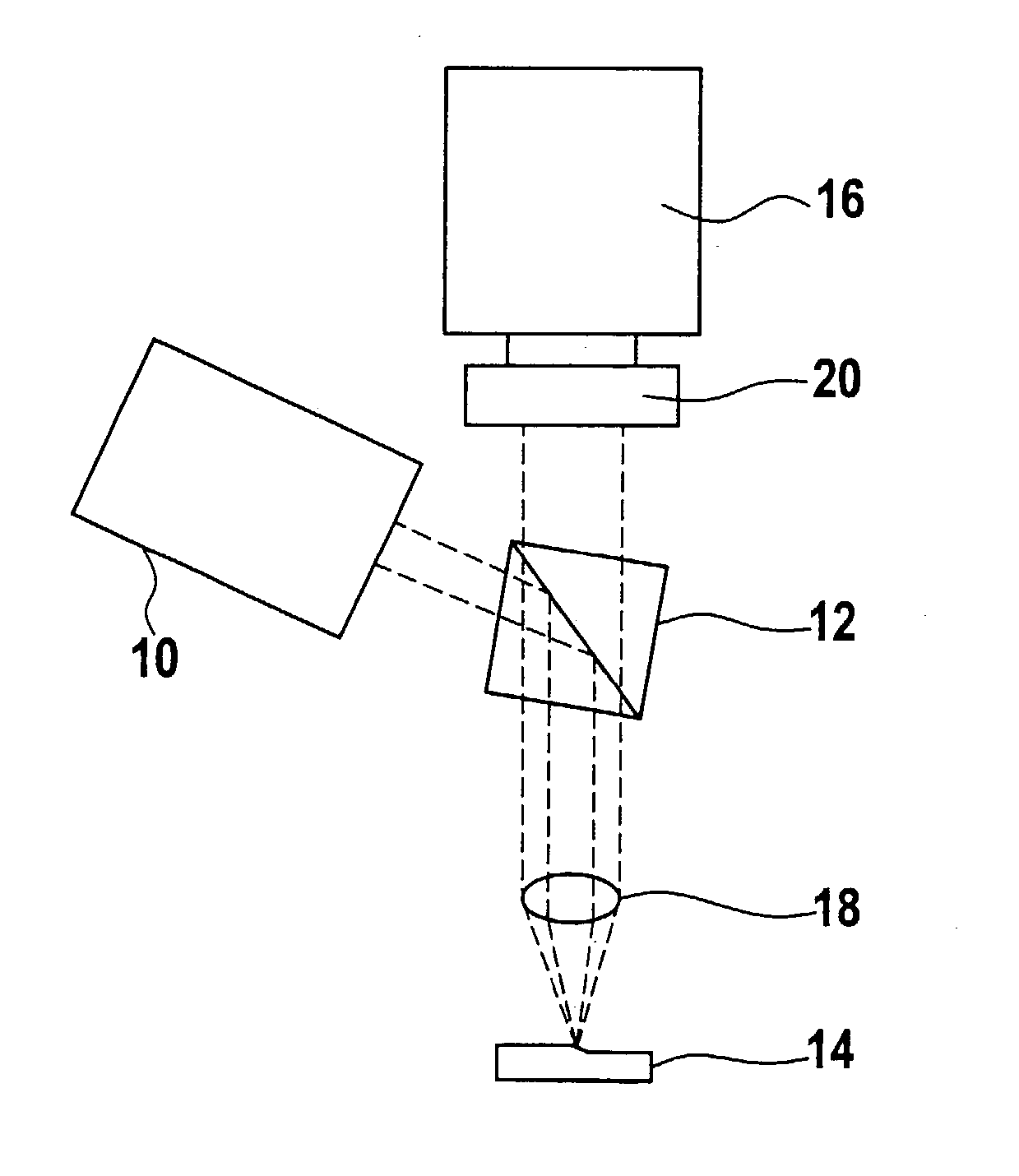
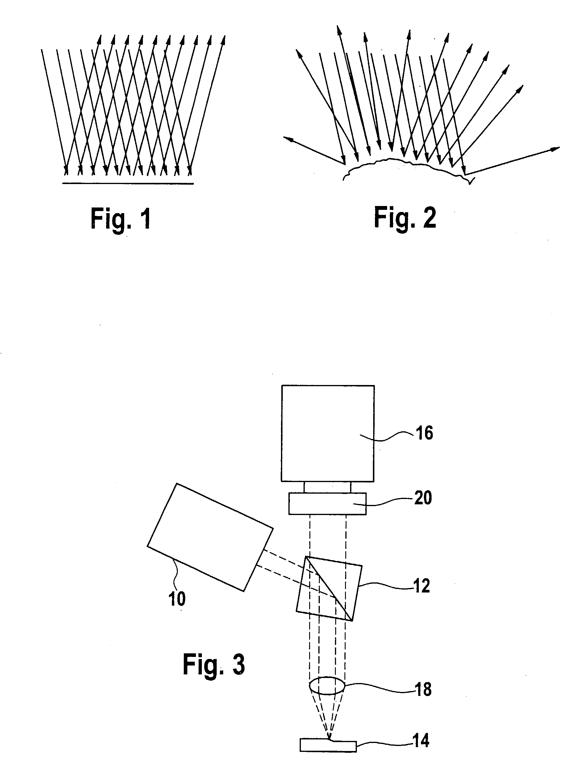
[0010] A method for identifying an object according to the invention comprises the following steps:

[0011] (a) selecting an intrinsic surface of an object to be recognized;

[0012] (b) illuminating at least one identification area in the intrinsic surface of the object to be recognized with coherent light and intercepting at least one portion of the light reflected by the identification area, in order to obtain an interference pattern under determined illumination and interception conditions;

[0013] (c) retaining this interference pattern as a reference interference pattern for the object to be recognized;

[0014] (d) placing a candidate object liable to be the object to be recognized under the same illumination and interception conditions as those used for obtaining the reference interference pattern and obtaining an interference pattern from this candidate object;

[0015] (e) comparing the reference interference pattern with the interference pattern of the candidate object; and

[0016] (f) ...


PUM

PropertyMeasurementUnit
surface areaaaaaaaaaaa
peak-to-peak roughnessaaaaaaaaaa
diameteraaaaaaaaaa

Abstract

The invention concerns a method for identifying an object comprising the following steps: (a) selecting an intrinsic surface of an object to be identified; (b) illuminating at least an identification zone in the intrinsic surface of the object to be identified with a coherent light and intercepting at least part of the light reflected by the identification zone, so as to obtain an interference figure in specific illuminating and intercepting conditions; (c) preserving said interference figure as reference interference figure of the object to be identified; (d) placing a candidate object which could possibly be the object to be identified in similar illuminating and intercepting conditions as those used to obtain the reference interference figure and obtain from said candidate object an interference figure; (e) comparing the reference interference figure with the interference figure of the candidate object; and (f) assessing the probability of identity between the object to be identified and the candidate object based on the degree of correspondence between the reference interference figure and the interference figure of the candidate object.

Description

[0001] The present invention relates to a method for identifying an object.STATE OF THE ART[0002] In order to identify each of the objects of a series of objects with identical appearance, the most standard method consists of fixing an identification plate on each object, each of the identification plates bearing a distinctive mark. However, if the identification plates are exchanged between several objects of the series, it is no longer possible to identify a particular object of the series with certainty.[0003] GB-A-2,221,870 relates to a security device for use in an optical method based on the speckle interferometry phenomenon, better known as the "speckle effect". The security device comprises a substrate whereon or wherein there is a structure scattering the radiations. This radiation-scattering structure when it is illuminated by a coherent ray of radiations, causes random scattering; the scattered rays then interfering to generate an interference pattern. It should be noted ...

Claims


Application Information

Patent Timeline
Patent Type & Authority Applications(United States)
IPC IPC(8): G07D7/12G01N21/84
CPCG06K9/00577G07D7/122G07D7/121G07D7/1205G06V20/80
Inventor D'AGRAIVES, BERTRAND CAUSSECHIARAMELLO, MICHEL
Owner EURON COMMUNITY EC
Learn More