Percutaneous cellulite removal system

a cellulite removal and percutaneous technology, applied in the field of percutaneous cellulite removal system, can solve the problems of not using an instrument, affecting the effect of any of these methods, and worsening the appearance of the skin

Inactive Publication Date: 2003-08-21
EXPANDING CONCEPTS
View PDF30 Cites 85 Cited by
  • Summary
  • Abstract
  • Description
  • Claims
  • Application Information

AI Technical Summary

Problems solved by technology

There are few scientific studies, however, that demonstrate the efficacy of any of these methods.
Removal of the subcutaneous fat by liposuction does not alter the dimpled appearance of the skin and, in fact, may worsen the appearance of the skin.
While this method represents a significant advance in the treatment of cellulite, a disadvantage of this method is that it uses an instrument that was not designed for the purpose of cutting fibrous bridges or septae.
The use of a liposuction cannula is invasive, awkward, imprecise, and physically difficult.
Because treatment of cellulite by breaking fibrous bridges or septae is a recent development, prior art surgical devices were not developed with this purpose in mind.
Each of the devices described would need to be used in the same manner that the liposuction cannula is employed in the Lieberman-Cohen method and suffers from the same and additional disadvantages.
A disadvantage of the Narayanan cannula is that the intensity of the ultrasonic wave would likely need to be increased substantially to sever fibrous tissue and this increase would likely result in unwanted ancillary damage to nearby tissue.

Method used


Image

  • Percutaneous cellulite removal system
  • Percutaneous cellulite removal system
  • Percutaneous cellulite removal system

Examples


Embodiment Construction

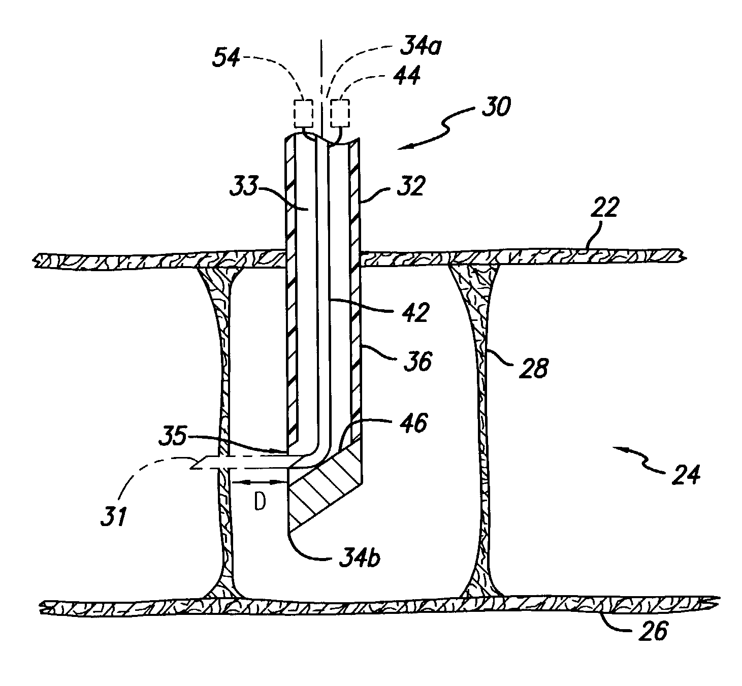
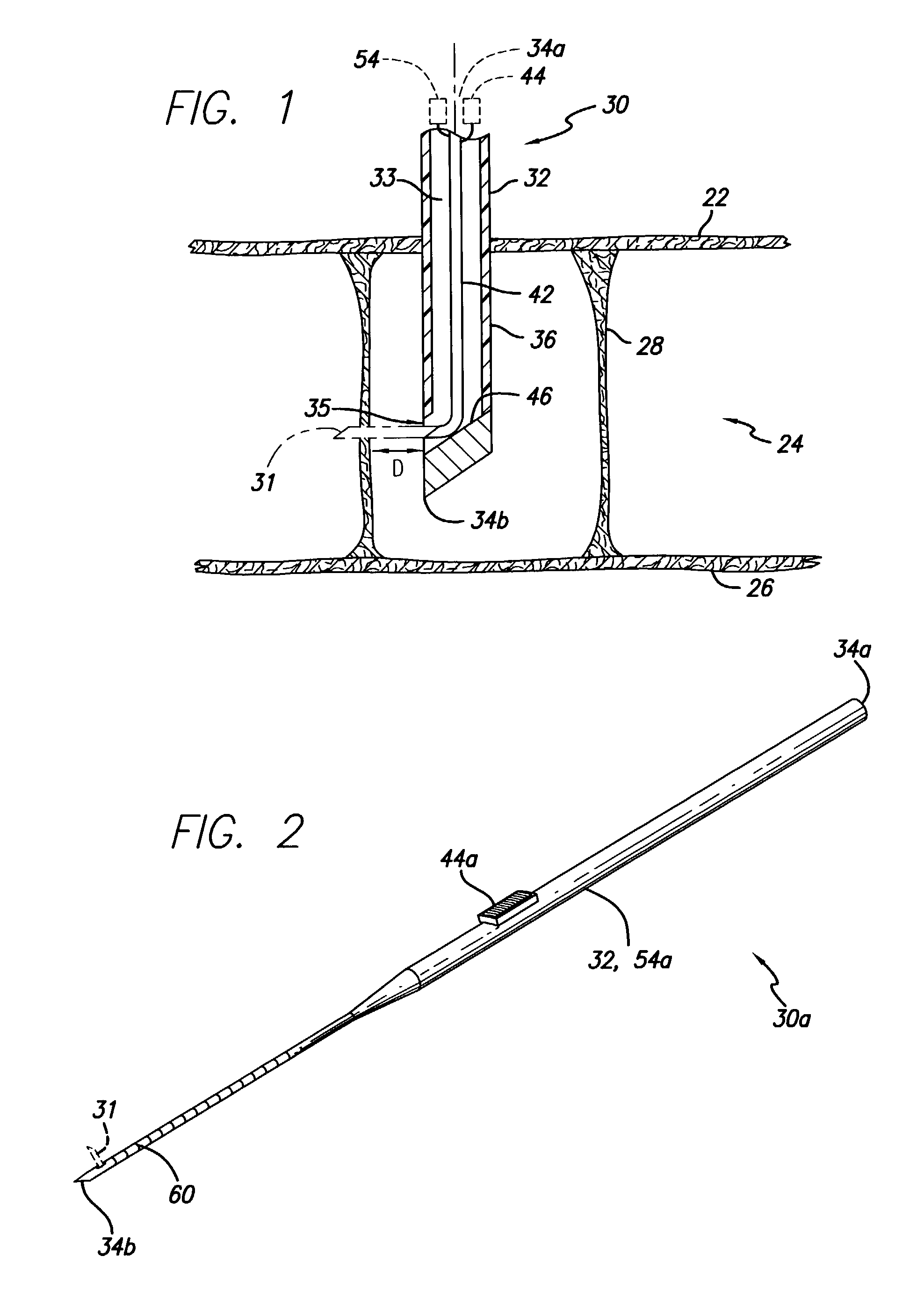
. Referring to in FIG. 2, a first exemplary preferred embodiment of the present invention of the percutaneous cellulite removal needle 30a includes a thick flexible and retractable blade 31. An extrusion mechanism is the situating mechanism 44a that controls the transition of the flexible blade 31 between a retracted position in which the flexible blade 31 is within the internal chamber 33 and a cutting position (in phantom) in which the flexible blade 31 extends through the lateral aperture 35 to the side of the percutaneous cellulite removal needle 30a. The plastic housing 32 serves as the actuating mechanism 54a as the surgeon rotates the housing 32 between his fingers so that the flexible blade 31 rotates to cut fibrous bridges 28.

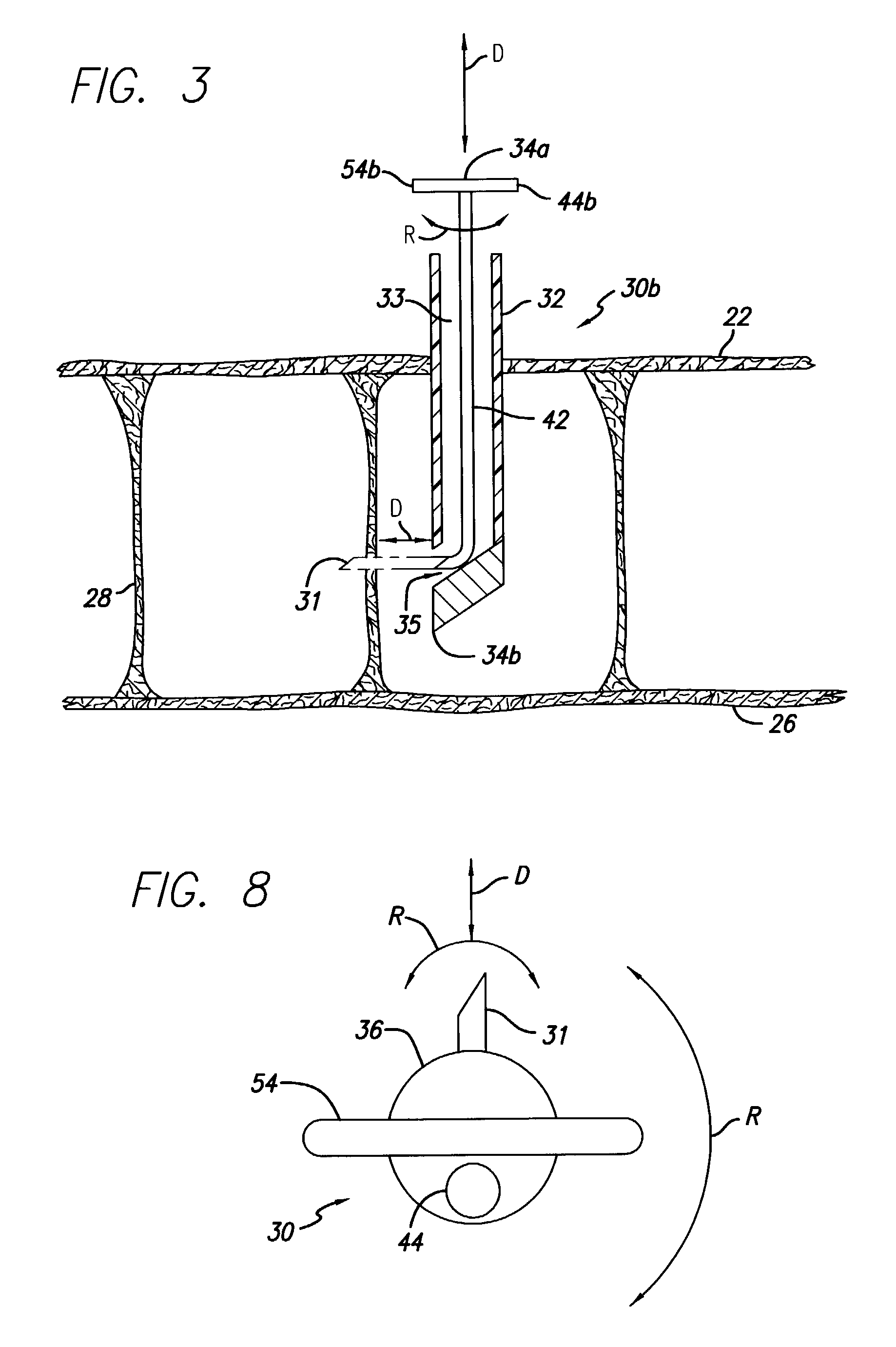
[0054] Second Embodiment Example. Referring to FIG. 3, a second exemplary preferred embodiment of the present invention of the percutaneous cellulite removal needle 30b includes a flexible and retractable blade 31 that is connected directly or indirect...


PUM


Abstract

A percutaneous cellulite removal needle of the present invention can be used to make the appearance of cellulite less obvious by cutting the fibrous bridges that connect the skin to muscle / fascia or fibrous septae in the subcutaneous fat in a minimally invasive manner. The percutaneous cellulite removal needle of the present invention preferably includes a body having an internal chamber that ends at a laterally disposed aperture. A cutting mechanism is substantially positioned within the internal chamber in a retracted position and at least partially protrudes through the laterally disposed aperture in a cutting position. A situating mechanism transitions the cutting mechanism between the retracted position and the cutting position. The present invention also includes a method in which the percutaneous cellulite removal needle is inserted through the skin with the cutting mechanism in the retracted position. The cutting mechanism is then extruded so that the cutting mechanism is in the cutting position. Next the cutting mechanism is actuated, for example by rotating, to cut at least one the fibrous bridge or septae. These steps may be repeated to cut other fibrous bridges or septae reachable by the cutting mechanism. The cutting mechanism is then retracted and the percutaneous cellulite removal needle is removed.

Description

[0001] The present application is based on, and claims priority from, U.S. Provisional Application Serial No. 60 / 332,355, filed Nov. 15, 2001 and U.S. Provisional Application Serial No. 60 / 356,891, filed Feb. 13, 2002, both of which are hereby incorporated herein by reference.BACKGROUND OF INVENTION[0002] The present invention relates to an apparatus and method for making the appearance of cellulite less obvious by cutting the fibrous bridges that connect the skin to muscle and / or fascia (hereinafter referred to as "muscle," "fascia," or "muscle / fascia") or by cutting the fibrous septae in subcutaneous fat in a minimally invasive manner, and specifically to a percutaneous cellulite removal needle with at least one lateral opening in its peripheral surface through which a surgical instrument and / or a cutting mechanism retracts or protrudes and methods for using the percutaneous cellulite removal needle.[0003] Cellulite is a popular term used to describe the dimpled or "lumpy skin" ap...

Claims


Application Information

Patent Timeline
Patent Type & Authority Applications(United States)
IPC IPC(8): A61B17/22A61B17/32A61B17/34
CPCA61B2017/22077A61B2017/320052A61M2202/08A61B17/3478A61B17/3403A61B17/3417A61B17/32093
Inventor BRETT, DARRELL C.
Owner EXPANDING CONCEPTS
Why Eureka
Try Eureka