Winding method and winding device

Inactive Publication Date: 2003-09-11
NITTOKU ENG CO LTD
View PDF13 Cites 26 Cited by
  • Summary
  • Abstract
  • Description
  • Claims
  • Application Information

AI Technical Summary

Problems solved by technology

However, although the direct winding methods (a) and (b) are applied to concentrated winding in which wires are wound in concentration onto each tooth, these methods cannot be applied to distributed winding in which wires are wound over a plurality of teeth.
If an attempt is made to perform distributed winding using the direct winding methods in (a) and (b), the wire of the initially wound phase over the slot causes an obstruction such that the wire to be wound in the following phases cannot be wound.
Even if the wires are inserted into

Method used


Image

  • Winding method and winding device
  • Winding method and winding device
  • Winding method and winding device

Examples


Embodiment Construction

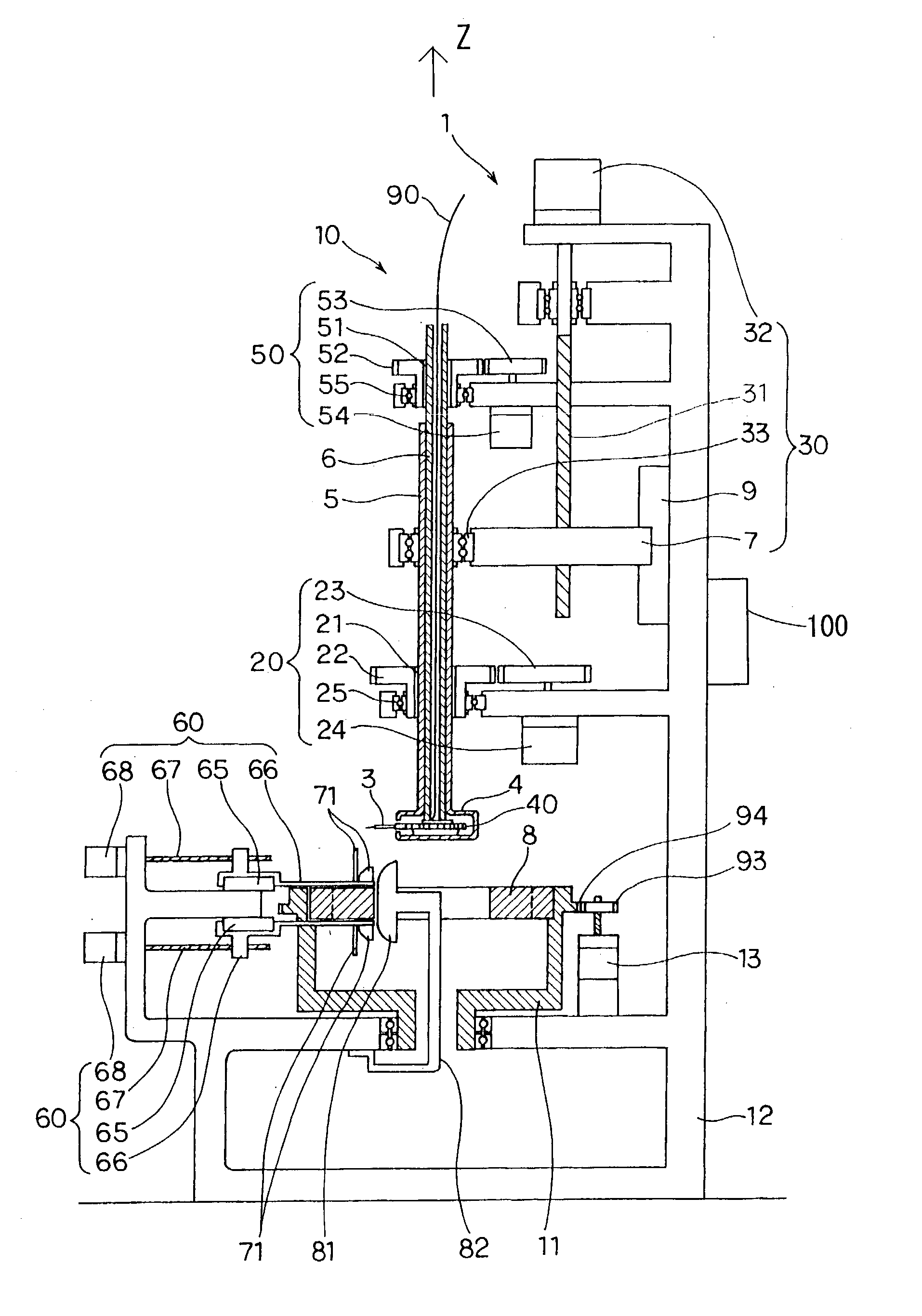
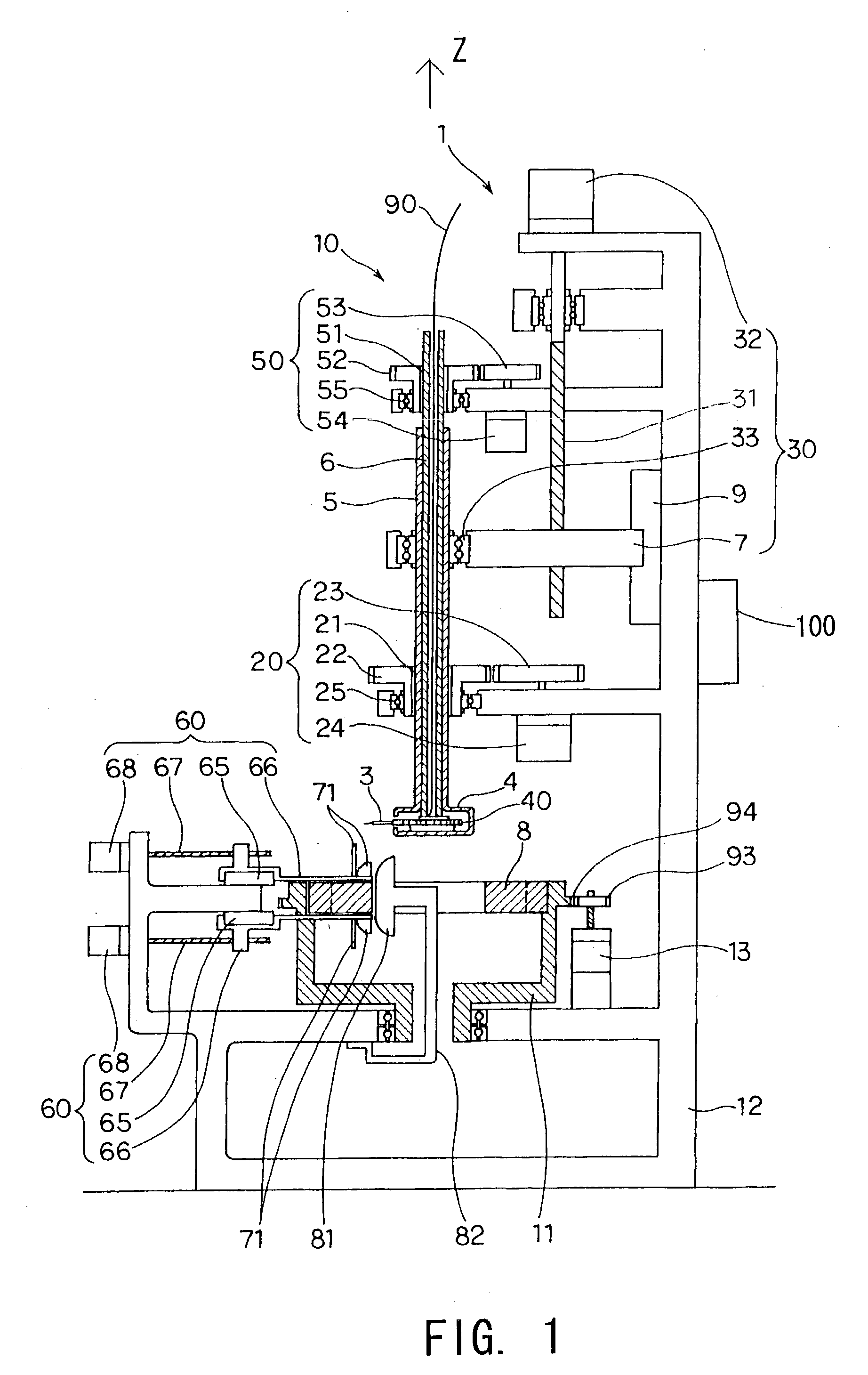
[0031] Embodiments of this invention will be described below on the basis of the drawings.

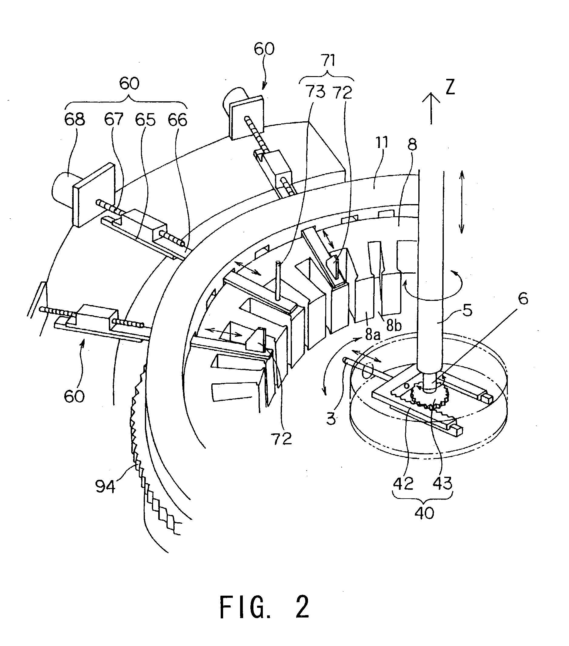
[0032] In FIGS. 1 through 12, a substantially cylindrical core 8 constitutes the stator of an inner rotor type three phase, four pole motor. The substantially cylindrical core 8 comprises a substantially cylindrical yoke and twenty-four teeth 8a (magnetic poles) which protrude from the yoke in a radial direction and are disposed at equal angles and intervals. Slots 8b are formed between adjacent teeth 8a. Distributed winding, in which the wire 90 is wound over five teeth 8a, is performed to form a stator coil.

[0033] Four sets of coils comprising each of the U, V, and W phase coils are formed along the peripheral direction. Each coil is comprised of a coil side portion 92 which is fitted into a slot 8b, a coil end portion 91 which emerges from the slot 8b and extends over five teeth 8a, and a corner portion 103 between the coil side portion 92 and coil end portion 91. Each coil end portion 91 is...


PUM


Abstract

A winding device winds a wire (90) onto a core (8) having a plurality of teeth (8b) protruding from a yoke and having slots (8a) formed between each tooth (8b). The winding device winds the wire (90) by causing a nozzle (3) which lets out the wire (90) to perform a relative motion. The winding device is provided with pusher plates (72) which guide the wire (90) into the slots (8a), and inserts the wire (90) into the slots (8a) by causing the pusher plates (72) to move relative to the core (8).

Description

[0001] This invention relates to improvements in a winding method and winding device for winding a wire around the stator core of an electric motor or a generator.DESCRIPTION OF THE RELATED ART[0002] As conventional winding methods applied to an inner rotor type stator, a direct winding method in which a wire is directly wound onto teeth, and an inserter winding method in which a pre-wound wire is inserted into a slot are known. The following methods described in (a) and (b) are direct winding methods.[0003] (a) A direct winding method in which a wire is wound onto a core by inserting a nozzle which supplies the wire into the interior of each slot.[0004] (b) A direct winding method in which a wire is wound onto a core by moving the nozzle which supplies the wire on the outside of each slot.[0005] The following method described in (c) is an inserter winding method.[0006] (c) An inserter winding method in which a wire is wound in advance onto a rod-shaped member disposed along the ins...

Claims


Application Information

Patent Timeline
IPC IPC(8): H02K15/06H02K15/085
CPCH02K15/06Y10T29/49009H02K15/085H02K3/46
Inventor KOMURO, KATSUROUIGARASHI, ITARU
Owner NITTOKU ENG CO LTD
Why Eureka
Try Eureka