Liquefaction phenomenon prediction system

a prediction system and phenomenon technology, applied in the direction of simultaneous indication of multiple variables, electrical/magnetic measuring arrangements, vibration measurement in solids, etc., can solve the problems of insufficient universalization of soil behavior, insufficient complexity of soil in situ behavior, and inability to explain a real phenomenon

Inactive Publication Date: 2003-09-25
TOHOKU TECHNO ARCH CO LTD
View PDF8 Cites 20 Cited by
  • Summary
  • Abstract
  • Description
  • Claims
  • Application Information

AI Technical Summary

Problems solved by technology

However, this method is a bipolar prediction method predicting either the liquefaction phenomenon occurs or not, and is not a method that can explain a real phenomenon where damage quantity continuously and relatively differs depending on a magnitude relationship between the size of external force and the size of resistance.
However, universalization of the behavior of soil is not sufficient by the current technical level, and the complexity of the behavior of soil in situ has not been fully expressed.
Further, there has existed a problem that the conventional numerical analysis incorporated large uncertainty in modeling the cyclic shear behavior of soil.
In particular, the behavior of soil after it suffered shear stress and its strain level became large is extremely important because it directly contributes to the residual deformation quantity of ground, but no ultimate solution exists in modeling this area.

Method used


Image

  • Liquefaction phenomenon prediction system
  • Liquefaction phenomenon prediction system
  • Liquefaction phenomenon prediction system

Examples


Embodiment Construction

[0025] Preferred embodiments of the present invention will be described using the accompanying drawings.

[0026] The present invention is a system that replaces the cyclic shear behavior of soil not with a numerical model but with behavior that is directly obtained from element test for a soil sample in situ. In the present invention, this system can find the residual settlement quantity and the residual horizontal displacement of ground.

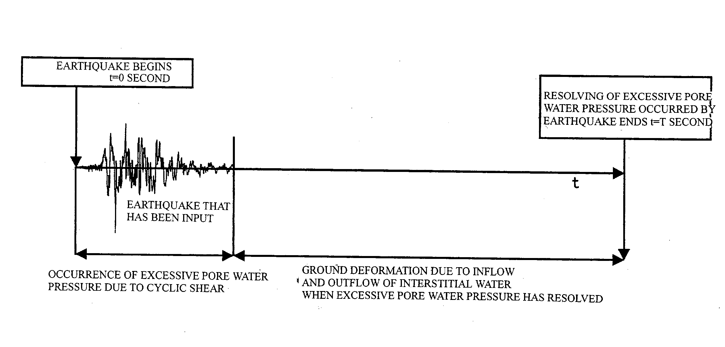
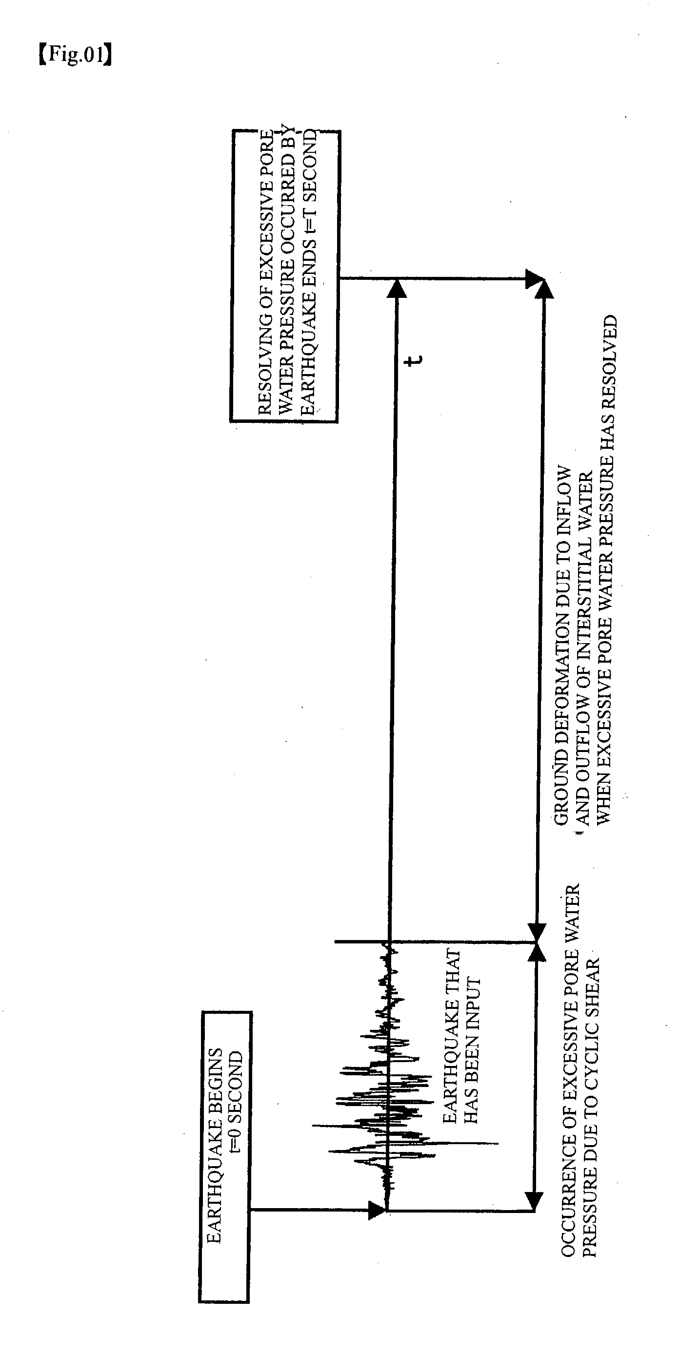
[0027] Furthermore, to predict the shear strain quantity that progressively develops after vibration, the present invention is a prediction system of seepage flow deformation quantity after earthquake, which has directly incorporated the behavior of soil element in situ as well as during earthquake using a seepage flow analysis that has incorporated mechanism where excessive pore water pressure occurred during earthquake penetrates and moves after vibration and ground thus fails and deforms.

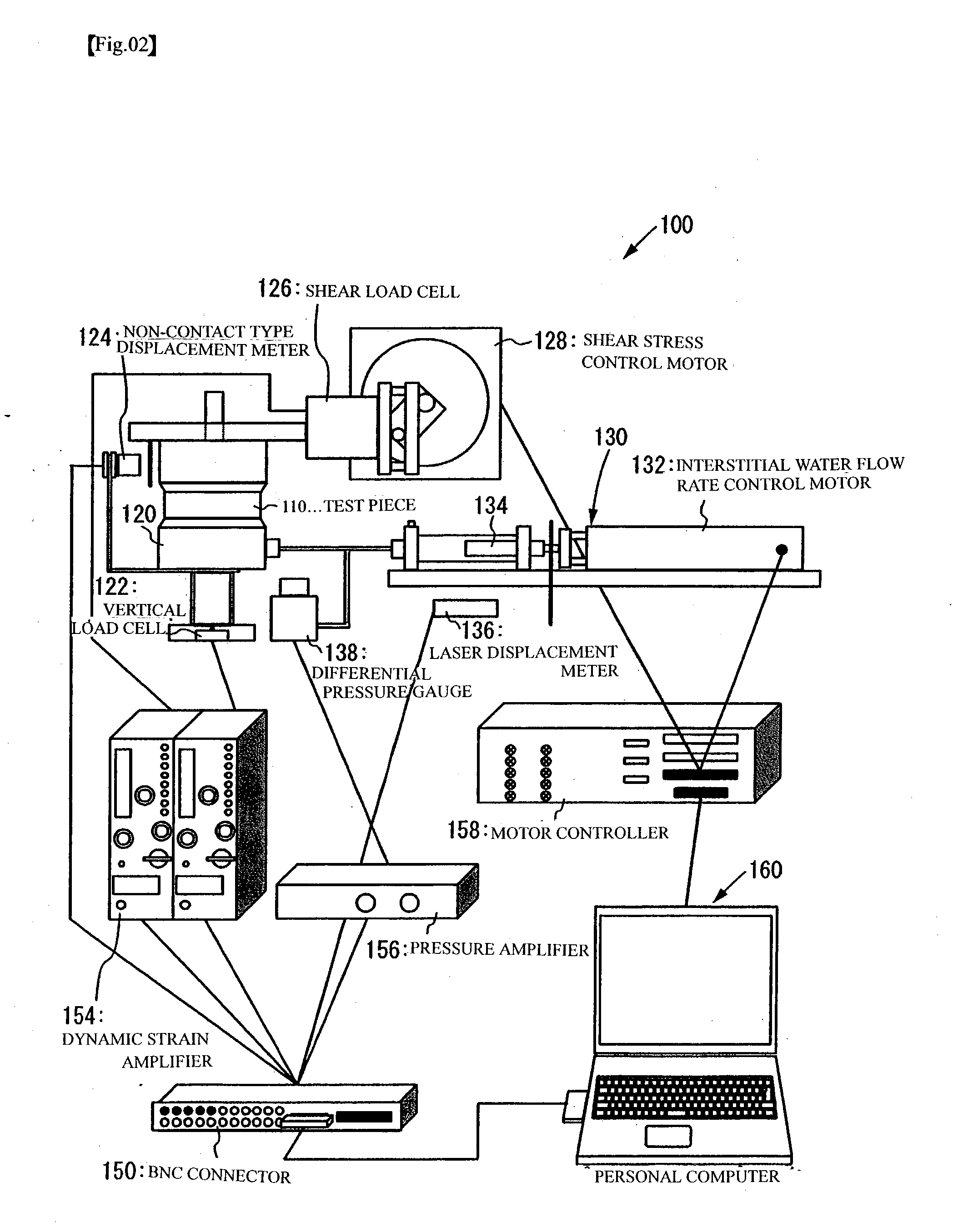
[0028] FIG. 2 shows the entire experimental apparatus 100 use...


PUM

PropertyMeasurementUnit
shear stressaaaaaaaaaa
interstitial wateraaaaaaaaaa
pore water pressureaaaaaaaaaa

Abstract

To predict residual settlement quantity and residual horizontal deformation quantity of ground where a liquefaction phenomenon has occurred due to earthquake. Soils in situ (stratum B to stratum D) are sampled from ground, and are made to be element test object stratums. A stratum whose characteristic is well-known, or the like may be substituted for a numerical model (stratum A). Next, setting of input conditions is performed, and vertical stress, horizontal stress and initial shear stress, which are equivalent to applied load that the ground at a depth of the point suffers, are worked on to each stratum. This recreates a stress status of soil before earthquake occurs. Then, shear displacement and the movement quantity of interstitial water by earthquake are given to the test piece, and the quantity of shear stress and pore water pressure, which have occurred, is obtained. In the element test execution stratum, displacement computed for stratum element and the movement quantity of interstitial water are actually given to each element to measure restoring force and the pore water pressure. By sequentially repeating the steps, it is possible to simulate the behavior of the liquefaction phenomenon.

Description

[0001] 1. Field of the Invention[0002] The present invention relates to a system to predict residual settlement quantity and residual horizontal deformation quantity of ground where a liquefaction phenomenon occurred due to earthquake.[0003] 2. Prior Art[0004] Liquefaction of ground is a phenomenon where cyclic shear stress due to earthquake motion increases pore water pressure in saturated sandy ground and reduces shear rigidity of ground. It is the phenomenon where settlement of ground or buildings, floating of light-weight underground structure, damage of piles due to a lateral flow phenomenon, is occurred by reduction of ground rigidity. Because random settlement of buildings or enormous damage occurs to infrastructure facility commencing with lifeline if the liquefaction phenomenon occurs, risk of the liquefaction phenomenon occurrence is predicted before constructing facility, and measures are taken for liquefaction if necessary.[0005] Conventionally, there has existed a metho...

Claims


Application Information

Patent Timeline
Patent Type & Authority Applications(United States)
IPC IPC(8): E02D27/34E02D1/00G01H17/00G01M7/00G01M99/00G01N3/00G01N29/12G01N29/22G01N29/44G01N33/24G06F17/50
CPCG01N29/12Y02T10/82G01N29/4418G01N29/222
Inventor KAZAMA, MOTOKISENTOU, NORIAKIYAMAGUCHI, AKIRA
Owner TOHOKU TECHNO ARCH CO LTD
Why Eureka
Try Eureka