Method of crosscutting a moving web

a technology of moving webs and cross-cutting, applied in the direction of stock shearing machines, manufacturing tools, transportation and packaging, etc., can solve the problem of practical limitations when implemented

Inactive Publication Date: 2003-10-02
MANROLANAD AG
View PDF2 Cites 13 Cited by
  • Summary
  • Abstract
  • Description
  • Claims
  • Application Information

AI Technical Summary

Problems solved by technology

Consequently, this presents practical limitations when implemented.

Method used


Image

  • Method of crosscutting a moving web
  • Method of crosscutting a moving web
  • Method of crosscutting a moving web

Examples


Embodiment Construction

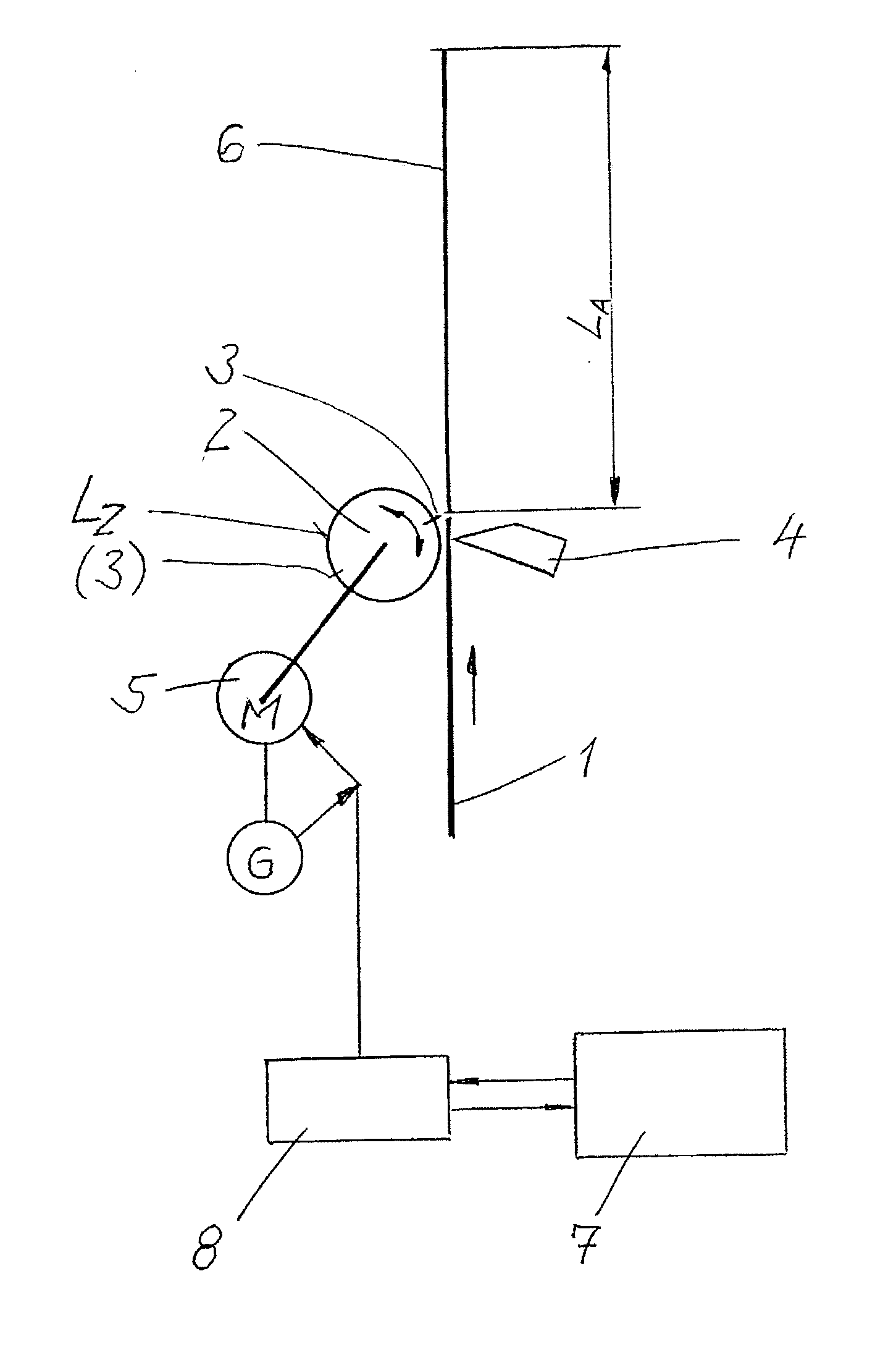
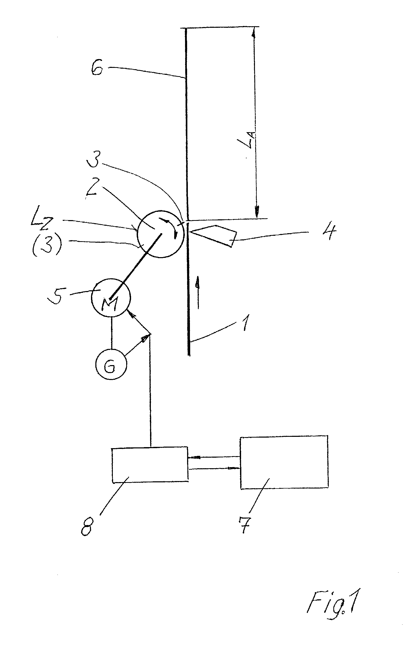
[0014] The apparatus for cross-cutting a web 1, shown in FIG. 1, includes a knife cylinder 2 fitted with at least one cutting knife 3 which during the rotation of the knife cylinder 2 rotates about its axis of rotation, wherein the axis of rotation is parallel to the cutting line. The axis of rotation is indicated by the curved double-headed arrow. Therein, the axis is perpendicular to the plane of FIG. 1.

[0015] The cutting knife 3 cooperates with an opposing knife 4 which is arranged in a fixed position. While the opposing knife 4 may rotate about an axis, it may also be designed as a cutting bar. Such a cutting bar may, for example, be housed in a folding cylinder, for example as a folding-blade cylinder of a folder. The cutting knife 3 and the opposing knife 4 can advantageously be arranged with an angular offset in relation to the cutting line to be made. This may advantageously produce a shearing cut.

[0016] It is also possible for a plurality of cutting knives to be arranged di...


PUM

PropertyMeasurementUnit
circumferential distance LZaaaaaaaaaa
cut length LAaaaaaaaaaa
speedaaaaaaaaaa

Abstract

A method of cross-cutting a moving web uses a cutting knife operably mounted on a knife cylinder having a circumferential distance LZ where LZ is smaller than a cut length, LA. The knife cylinder for revolving in a first and a second opposite direction is powered by a drive motor in either direction. The method includes revolving the knife cylinder in a first direction, cutting the web with the cutting knife, and completing a first cut. The knife cylinder is then reversed to retard progress in the first direction and then accelerated to the speed of the moving web until starting the second cut.

Description

[0001] 1. Priority Claim[0002] This application claims priority to application DE 102 13 978.4 filed Mar. 28, 2002 in Germany.[0003] 2. Field of the Invention[0004] The invention relates to a device for and a method of cross-cutting a moving web using a knife cylinder having at least one cutting knife which rotates about an axis parallel to the cutting line.[0005] 3. Description of the Related Art[0006] DE 100 30 055 Al discloses a method of cross-cutting a web using a knife cylinder. In order to vary the length of the cut products, i.e. vary the cut length, other than during cutting, the knife cylinder is driven at a circumferential speed that differs from the speed that the web is advanced. When small cut lengths or when the knife cylinder has a plurality of cutting knives distributed uniformly over the circumference, the speed change has to be completed during a small amount of circumferential travel. This requires high accelerations and powerful up-shifting, i.e. acceleration to...

Claims


Application Information

Patent Timeline
Patent Type & Authority Applications(United States)
IPC IPC(8): B26D5/20B65H35/08
CPCB26D5/20B65H2513/41B65H2513/212B65H35/08Y10T83/4847Y10T83/0519Y10T83/483Y10T83/4775B65H2513/23
Inventor KERSCH, ROBERTZELLER, WOLFGANG
Owner MANROLANAD AG
Why Eureka
Try Eureka