Remote monitoring of switch network

a switch network and remote monitoring technology, applied in the field of computer network management, can solve the problems of consuming a substantial amount of network system processing bandwidth by snmp agents in analyzing such raw data to determine the state of their respective local objects, consuming a substantial amount of stacked switch communications bandwidth, and rmon probes used in the aforedescribed conventional stacked switch monitoring arrangement are typically quite expensiv

Inactive Publication Date: 2003-10-02
CISCO TECH INC
View PDF1 Cites 50 Cited by
  • Summary
  • Abstract
  • Description
  • Claims
  • Application Information

AI Technical Summary

Problems solved by technology

The amount of network system processing bandwidth consumed by SNMP agents in analyzing such raw data to determine the states of their respective local objects can be significant.
Unfortunately, the RMON probes used in the aforedescribed conventional stacked switch monitoring arrang

Method used


Image

  • Remote monitoring of switch network
  • Remote monitoring of switch network
  • Remote monitoring of switch network

Examples


Embodiment Construction

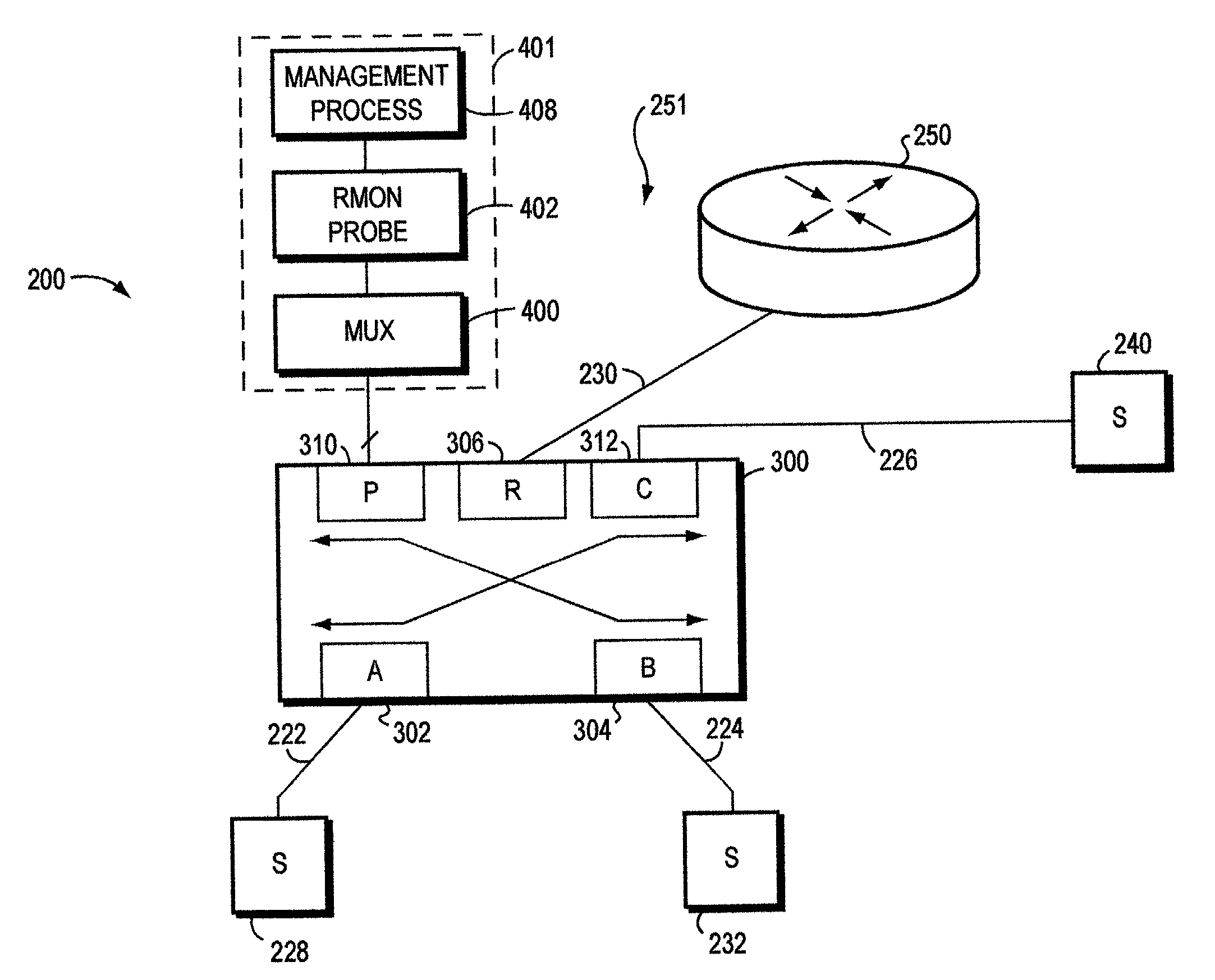
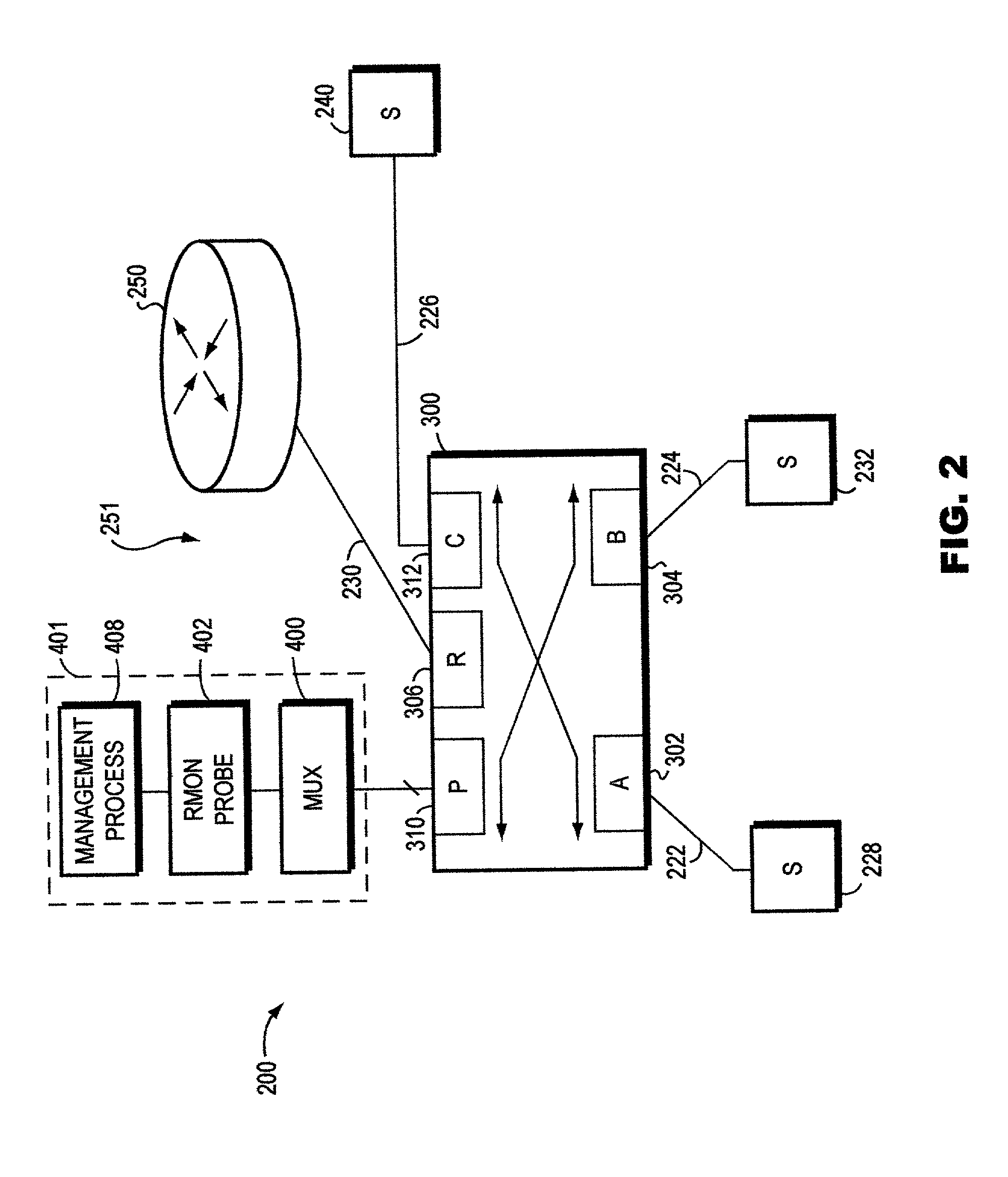
[0031] FIGS. 2-5 illustrate features of a computer network 200 wherein embodiments of the present invention may be advantageously practiced. Network 200 comprises a stacked switch network 300 which interconnects a plurality of network segments 228, 232, 240, and 251. Each segment 228, 232, 240 comprises one or more local area networks having computer endstations (not shown). Segment 251 is a network router segment that comprises network router 250. Each segment 228, 232, 240 is coupled via a respective communications link 222, 224, 226 to a respective port 302 (i.e., port A), 304 (i.e., port B), 312 (i.e., port C) of the switch network 300. Likewise, the router 250 of router segment 251 is coupled via a respective trunk line 230 to router port 306 (i.e., port R).

[0032] Each of the router 250, switches 300A, 300B, 300C (whose function and operation will be described more fully below), and endstations (not shown) of the segments 228, 232, 240, 251 typically comprises a plurality of in...


PUM


Abstract

A technique for use in gathering network activity-related information from cascaded network switches is provided. Using this technique, the information can be gathered without substantially reducing performance of the cascaded switches. In one embodiment, a single remote monitoring probe is connected via respective connections to each of the switches so as to receive the information from the switches. In another embodiment, only one of the switches is connected to the probe, and the other switches transmit their respective portions of the information to the switch connected to probe. The switch connected to the probe provides these portions of the information, as well as, any of its respective activity-related information to the probe. In this latter embodiment the switches may be connected by dedicated connections and switch ports that are used solely for communicating the activity-related information.

Description

[0001] 1. Field of the Invention[0002] The present invention relates generally to computer network management, and more specifically, to the remote monitoring of switch networks for purposes of facilitating management of such networks.[0003] 2. Brief Description of Related Prior Art[0004] Data communication in a computer network involves data exchange between two or more entities interconnected by communication links and subnetworks. These entities are typically software programs executing on hardware computer platforms, such as end-stations and intermediate stations. Examples of an intermediate station may be a router or switch which interconnects the communication links and subnetworks to enable transmission of data between the endstations. A local area network (LAN) is an example of a subnetwork that provides relatively short distance communication among the interconnected stations, whereas a wide area network enables long distance communication over links provided by public or p...

Claims


Application Information

Patent Timeline
IPC IPC(8): H04L12/26
CPCH04L43/12
Inventor NEDERVEEN, PAUL JOHANKING, ROBERT LEROY
Owner CISCO TECH INC
Why Eureka
Try Eureka