AI technical title is built by Patsnap AI team. It summarizes the technical point description of the patent document.
a technology of pole teeth and motors, which is applied in the direction of dynamo-electric machines, master clocks, magnetic circuit shapes/forms/construction, etc., can solve the problems of high manufacturing cost of core assemblies and difficulty in achieving a motor that is thinner in the axial direction
Inactive Publication Date: 2003-10-16
SANKYO SEIKI MFG CO LTD
View PDF0 Cites 2 Cited by
Summary
Abstract
Description
Claims
Application Information
AI Technical Summary
This helps you quickly interpret patents by identifying the three key elements:
Problems solved by technology
Method used
Benefits of technology
Benefits of technology
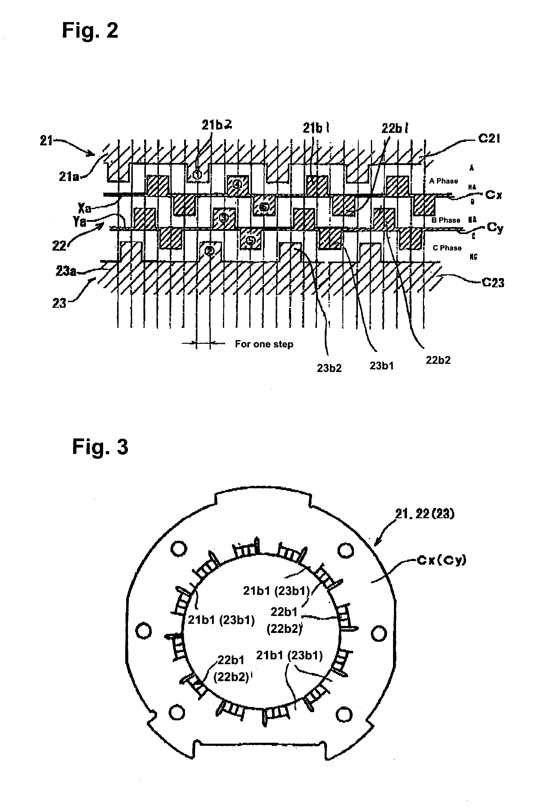
[0010] Due to the fact that the winding direction of the coil provided in one of the core assemblies that form three or more phases is set in a direction opposite to the winding direction of the coils provided in the other core assemblies, the pole teeth, which extend from the grip sections placed between the core assembly whose coil winding direction is set in the direction opposite to others and the adjacent core assemblies in the axial direction in both directions in the axial direction towards counterpart grip sections that form pairs with the grip sections, can be formed in positions and in a tooth width dimension that do not cause them to overlap one another in the axial direction. As a result, each of the grip sections placed between the core assembly whose coil winding direction is set in the direction opposite to others and the core assemblies adjacent to it in the axial direction can be formed from a single magnetic plate. Consequently, the structure of the core assemblies, and especially of the grip sections, can be made simple and thin.
[0009] In order to solve the problem, a motor in accordance with an embodiment of the present invention includes a plurality of core assemblies forming three or more phases; a plurality of coil windings provided on the respective core assemblies, wherein one of the coil windings is wound in a coil winding direction opposite to a coil winding direction of the coil windings on other of the coil assemblies; grip sections that are arranged in an axial direction to hold the core assemblies; and pole teeth extending from at least one of the grip sections in both directions in the axial direction, wherein the pole teeth do not overlap one another in the axial direction, and the at least one of the grip sections is formed from a single magnetic plate.
Problems solved by technology
In conventional motors, the grip sections 6a and 6a of the center core assembly 6 and one of the grip sections 5a and of the grip sections 7a of the end core assemblies 5 and 7, respectively, adjacent to the center core assembly 6 are forced to have a structure that forms one set from two pieces, as shown in FIGS. 11 and 12; this has resulted in higher manufacturing cost for the core assemblies and a difficulty in achieving a motor that is thinner in the axial direction.
Method used
Image
Click on the blue label to locate the original text in one second.
Reading with bidirectional positioning of images and text.
Examples
Embodiment Construction
[0028] Next, preferred embodiments that apply the present invention to stepping motors will be described with reference to the accompanying drawings.
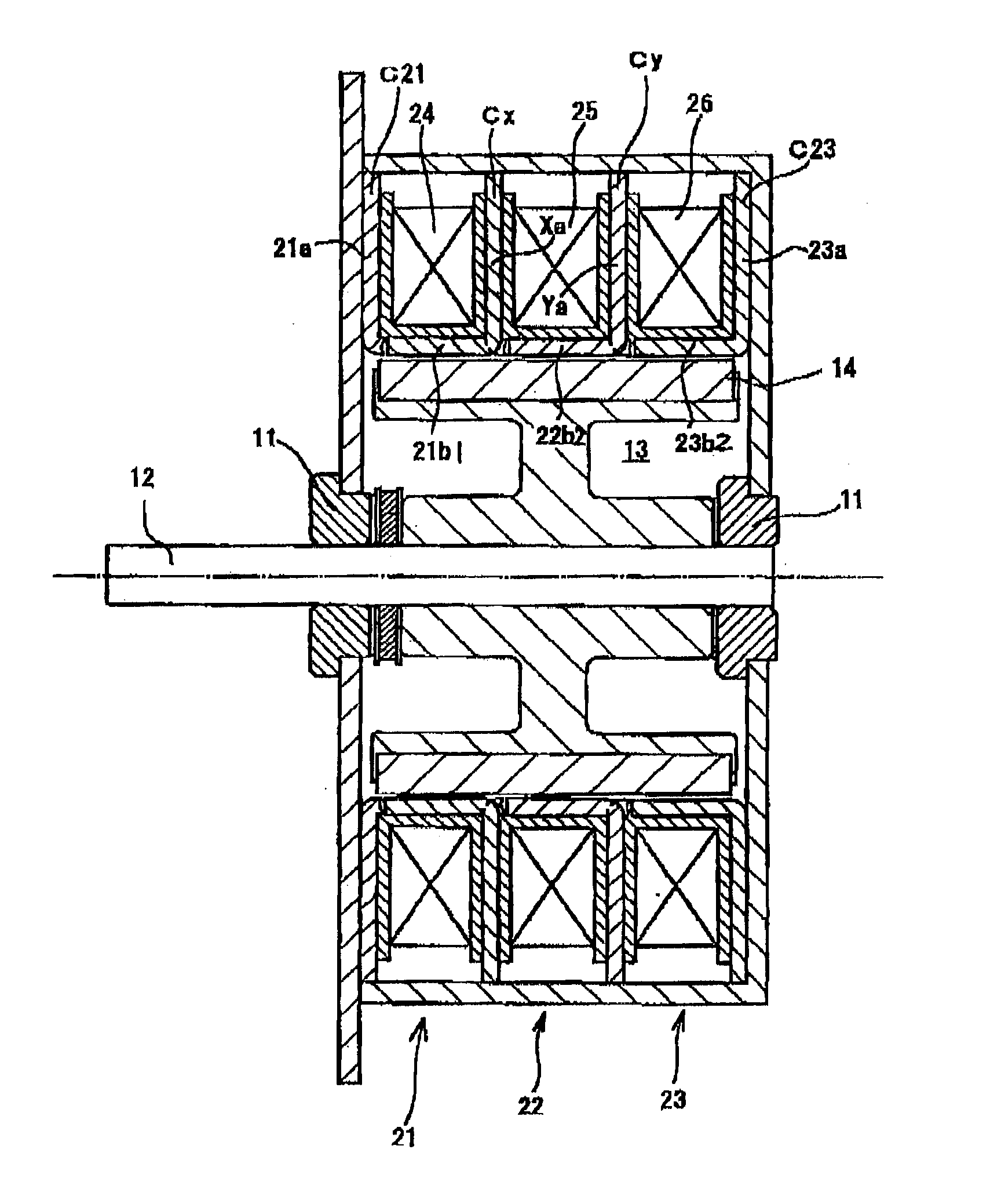
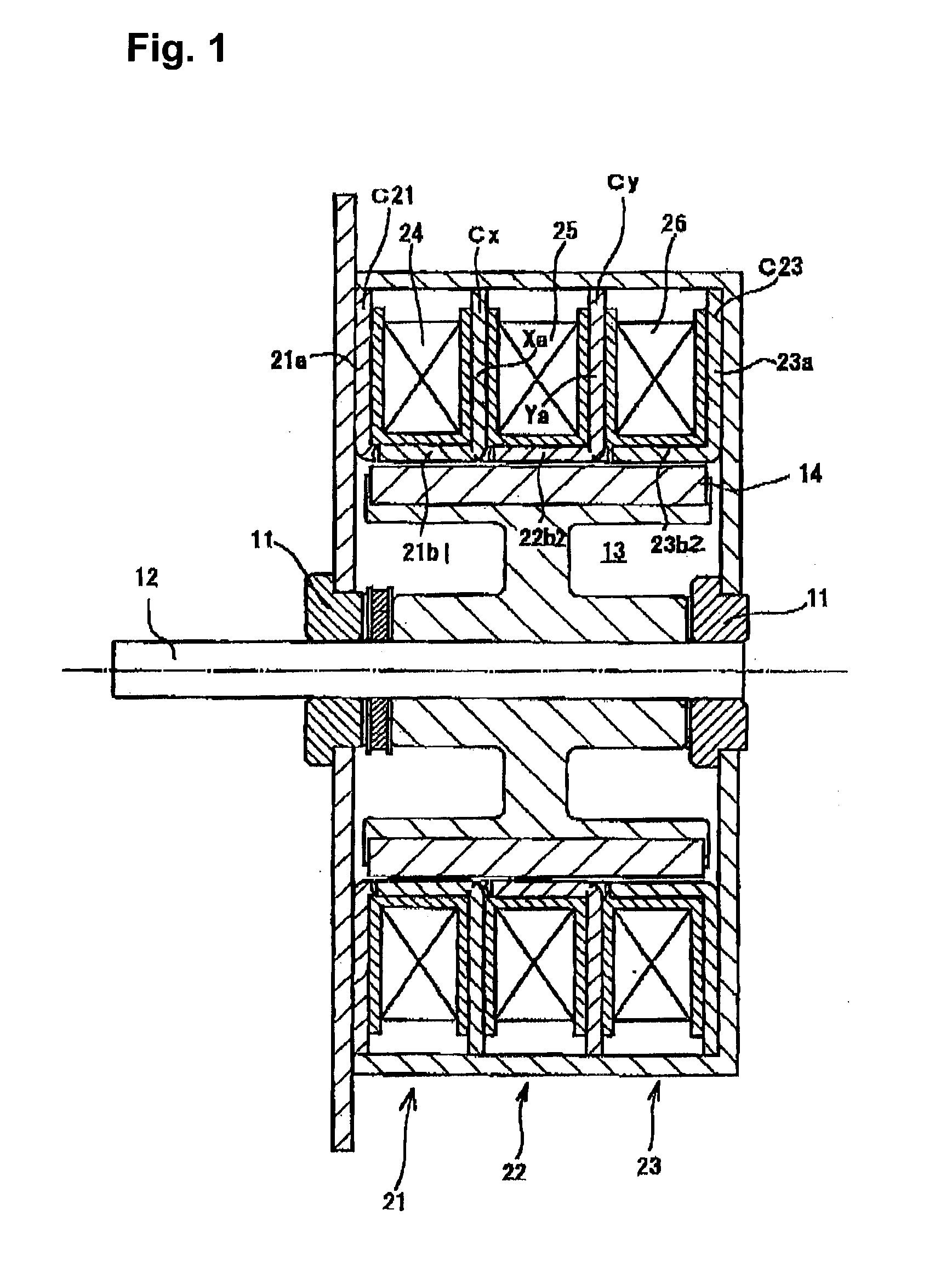
[0029] First, as shown in FIG. 1, a stepping motor includes a pair of bearing members 11 provided in a stator section, and a rotation shaft 12 that is supported in a freely rotatable manner by the bearing members 11. A rotor section 13 that is formed in a generally cylindrical shape is mounted on the rotation shaft 12. A rotor magnet 14 is mounted in a ring-shaped manner on the outer circumference surface of the rotor section 13. In close proximity on the outer circumference side of the rotor magnet 14 are core assemblies 21, 22 and 23 of the stator section provided overlapping and adhering to each other in the axial direction to form three phases in the axial direction. The core assemblies 21, 22 and 23 are provided with coils 24, 25 and 26, respectively, wound cylindrically around the rotation shaft 12.
[0030] Hereafter, the core place...
PUM
Abstract
A motor includes a plurality of core assemblies forming three phases, and a plurality of coil windings provided on the respective core assemblies, wherein one of the coil windings is wound in a coil winding direction opposite to a coil winding direction of the coil windings on other of the coil assemblies, grip sections that are arranged in an axial direction to hold the core assemblies, and pole teeth that connect to at least two of the grip sections on both sides of the center one of the core assemblies and extend from each of the two grip sections in both directions in the axial direction. The pole teeth extending in both directions from each of the two grip sections are arranged along a circumferential direction so as not to overlap one another in the axial direction, and the at each of the grip sections is formed from a single magnetic plate.
Description
[0001] 1. Field of the Invention[0002] The present invention relates to a motor with a plurality of pole teeth provided circumferentially adjacent to one another.[0003] 2. Related Background Art[0004] FIG. 9 shows a motor including core assemblies 5, 6 and 7 that are placed overlapping in the axial direction to form a plurality of phases, wherein the core assemblies 5, 6 and 7 have coils 2, 3 and 4, respectively, that are wound generally cylindrically on a rotation shaft 1.[0005] In the motor having such a structure, the core assemblies 5, 6 and 7 that form three phases are provided with pairs of disk-shaped grip sections 5a, 5a, 6a, 6a and 7a, 7a, respectively, that grip the coils 2, 3 and 4, respectively, in the axial direction. From the inner circumference end edge sections of the pairs of grip sections 5a, 5a, 6a, 6a and 7a, 7a extend pole teeth 5b1, 5b2, 6b1, 6b2, and 7b1, 7b2, respectively, that bend generally perpendicularly in the axial direction towards the counterpart in e...
Claims
Application Information
Patent Timeline
Application Date:The date an application was filed.
Publication Date:The date a patent or application was officially published.
First Publication Date:The earliest publication date of a patent with the same application number.
Issue Date:Publication date of the patent grant document.
PCT Entry Date:The Entry date of PCT National Phase.
Estimated Expiry Date:The statutory expiry date of a patent right according to the Patent Law, and it is the longest term of protection that the patent right can achieve without the termination of the patent right due to other reasons(Term extension factor has been taken into account ).
Invalid Date:Actual expiry date is based on effective date or publication date of legal transaction data of invalid patent.

