Pinch grip hanger

a technology of grip hanger and grip handle, which is applied in the field of grip hanger, can solve the problems of increasing the time and labor cost of loading the grip hanger, reducing the number of grip hangers that can be shipped on any given support bar, and relatively thick grip hanger with modest jaw opening

Inactive Publication Date: 2003-11-13
PROSPERITY PROD HK LTD
View PDF64 Cites 44 Cited by
  • Summary
  • Abstract
  • Description
  • Claims
  • Application Information

AI Technical Summary

Benefits of technology

[0016] It is another object of the invention to provide a secure and protected pinch grip hanger of reduced width having a relatively wide jaw opening to facilitate insertion of garments.
[0017] It is another object of the invention to provide a secure and protected pinch grip hanger of reduced width that has a multi-stage spring to provide a relatively constant bias force as the jaws are opened, thus minimizing the total force necessary to fully open the pinch grip.
[0018] It is another object of the invention to provide a secure and protected pinch grip hanger of reduced width having a relatively long grip to facilitate insertion of a waistband of a garment above the gripping members.

Problems solved by technology

This could result in increased time and labor costs to load the hanger and complaints of inadvertently broken finger nails from retail store personnel were common, with occasional repetitive stress injury complaints from factory workers who were loading thousands of garments a day into hangers of this style.
The design of the pinch grip utilized in this device results in a relatively thick hanger with a modest jaw opening.
While these designs achieve their intended effect, they are relatively thick, reducing the number of hangers that can be shipped on any given support bar.
Further, as a result of the pinch grip design utilized, the maximum opening of the pinch grip is limited.
However, in this design, pressing two adjacent hangers together would result in opening the pinch grip, and release of the garment.
This makes it difficult to fully open the jaws of some of these hangers when it is necessary to insert a relatively thick waistband.
At a minimum, four manual steps or movements are required for each garment that is loaded, resulting in relatively high labor costs for loading the garments.
These prior art hangers are difficult to automate as they are not designed to stack load in a magazine, and they frequently have a single pair of projecting high points which causes the hangers to not stack evenly in a magazine.
Further, the high points can result in the hanger snagging on the next to be fed hanger in an automated feed mechanism.

Method used


Image

  • Pinch grip hanger
  • Pinch grip hanger
  • Pinch grip hanger

Examples


first embodiment

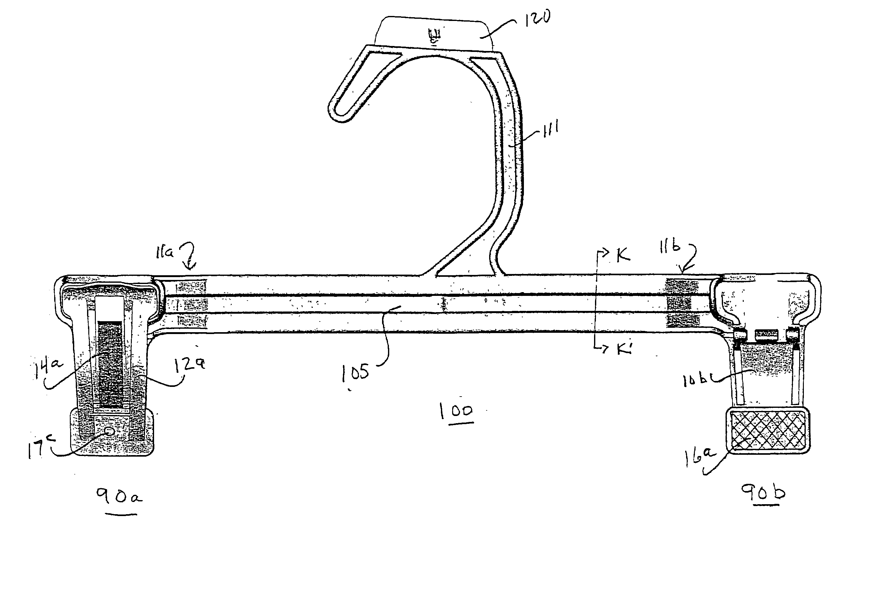
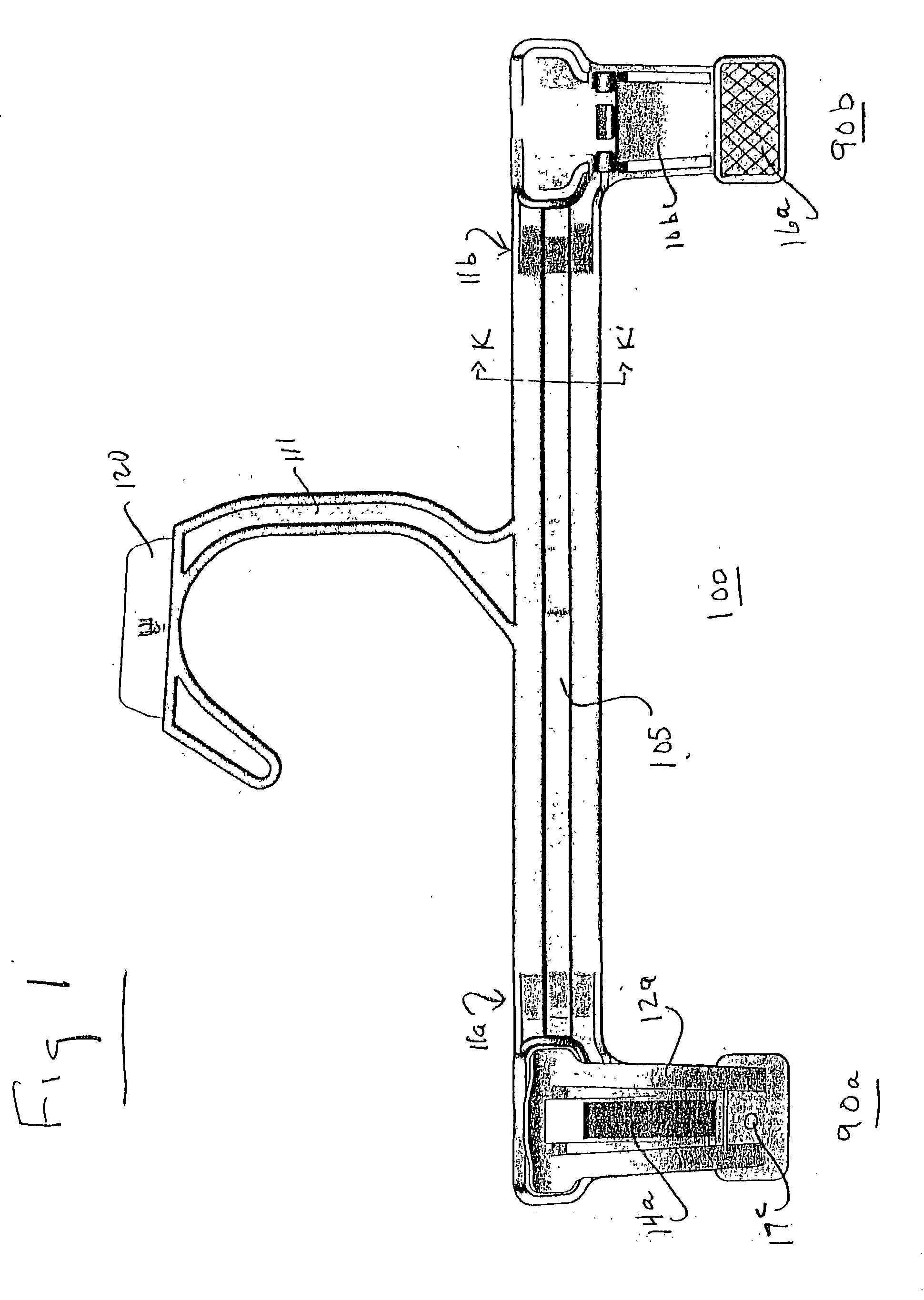
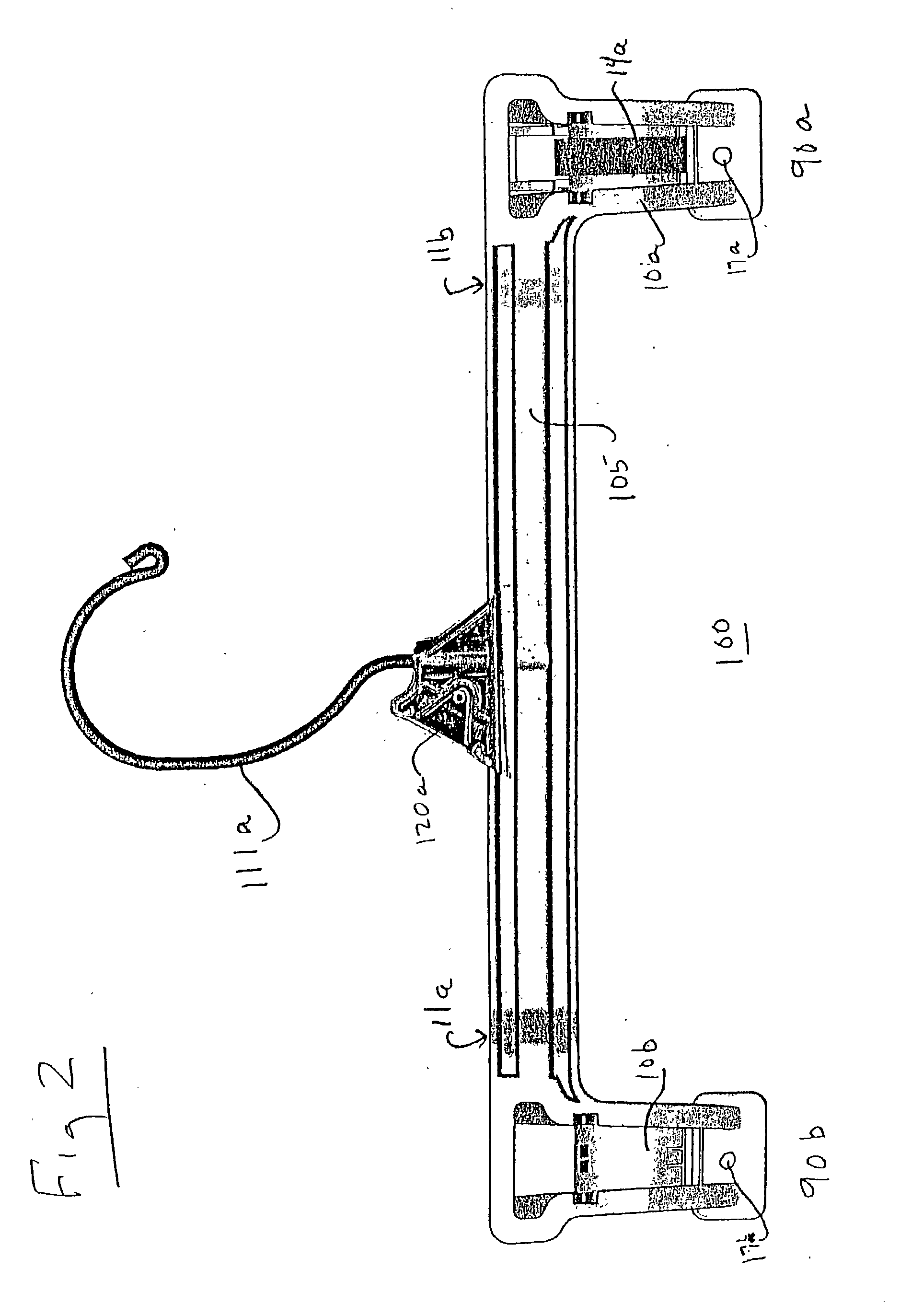
[0056] In the invention, integrally molded teeth are used to engage the garment. As illustrated in FIGS. 3c, 3d, 6d-6f, and 7, the teeth 16c and 16d are integrally molded onto the pinch grips 10b and 12b. Although only one set of teeth is illustrated in FIGS. 3c, 3d, and 6d-6f, a plurality of teeth can exist on either or both the movable jaw 12b or the fixed jaw 10b, as illustrated in FIG. 7.

[0057] The teeth 16c, 16d are very effective in retaining garments within the hanger. The increased retention power of the teeth 16c, 16d is derived from channeling the full retention power of the spring member 14a or 14b through the narrow contact area of the teeth 16c, 16d, as compared to alternative gripping surfaces. Accordingly, the teeth 16c, 16d of the elongated pinch grip hangers are particularly suited for rugged and heavy garments such as denim jeans with wide waistbands. Garments made of rugged material have relatively more resiliency than, for example, garments suitable for casual or...

second embodiment

[0062] the invention uses non-slip pads rather than teeth to genage the garments. When non-slip pads are used as the garment engaging means, the non-slip pads 16a are formed from a thermoplastic rubber such as Raplan, or the Kraton family of materials manufactured by Shell Oil Company. This material has a high coefficient of friction when engaging a fabric, and is durable enough to maintain pad integrity during repeated clamping cycles. The pads 16a are post molded by injection molding through openings 17a and 17b in the fixed jaw and openings, and openings 17c and 17d in the moveable jaws into corresponding recesses on the garment engagement side, such as recess 16b in FIG. 3a. As illustrated in FIGS. 1 and 3b, the pads are also lightly textured to enhance the non-slip grip on fabric. To facilitate the retention of the pad in the recess, an amount, preferably 15%, of the hanger host plastic material may be added to the thermoplastic rubber prior to molding the pad. Depending on the...


PUM


Abstract

An improved pinch grip pant and skirt hanger of reduced depth and elongated grip is formed for gripping garments below the waistband. The pinch grip has an offset between the hanger bar and the mounting of the pinch grip to align the center axis of the hanger bar with the center of the pinch grip, to thereby reduce the depth of the hanger and pinch grip and provide greater density of garments during shipment. Two separate guards are provided to prevent inadvertent opening of the pinch grip by an adjacent hanger, including a moveable guard, formed by arches on the fixed and moveable jaws. Since the arches are formed to contact below the pivot axis of the pinch grip, any contact between hangers will serve to enhance grip, rather than inadvertently opening the pinch grip. The hanger is particularly adapted for magazine feed and the automated loading of garments.

Description

[0001] This is a Continuation-in-Part of U.S. application Ser. No. 10 / 076,790, filed Feb. 15, 2002.[0002] The present invention relates generally to a pinch grip hangers, and more particularly pertains to a pinch grip hanger used for hanging pants and skirts for shipment to retailers and display of the same in a retail environment. The improved hanger has reduced depth, a greater jaw opening, a greater jaw length, and more constant spring force than prior art hangers.[0003] Consumer taste and fashion have dictated a desire for mass-produced, but well-fitted garments, which are distributed and sold throughout the United States. Large national retailers of clothing generally contract with a plurality of clothing manufacturers to produce uniform standardized clothing, which is essentially identical from batch to batch, even though manufactured by different entities. These manufacturers in turn produce the clothing at their own plants, or in many cases, subcontract the production of the...

Claims


Application Information

Patent Timeline
Patent Type & Authority Applications(United States)
IPC IPC(8): A47G25/14A47G25/48
CPCA47G25/1442A47G25/1421A47G25/1435A47G25/485A47G2025/484A47G25/32A47G25/34A47G25/483
Inventor GOULDSON, STANLEY F.OLK, OLAF
Owner PROSPERITY PROD HK LTD
Why Eureka
Try Eureka