Method of and system for flushing one or more cells in a particle-based electrochemical power source in standby mode

a technology of electrochemical power source and particle-based electrochemical, which is applied in the direction of separation process, basic electric element, electric apparatus, etc., can solve the problems of particle buildup, recirculation and electrochemical reaction can have undesired consequences, and reduce the flow of reaction solution through the anode bed

Inactive Publication Date: 2003-11-20
METALLIC POWER INC
View PDF99 Cites 9 Cited by
  • Summary
  • Abstract
  • Description
  • Claims
  • Application Information

AI Technical Summary

Problems solved by technology

Particle-based electrochemical power sources, including without limitation metal-based fuel cells, which employ particulate anodes and which deliver reaction agents such as hydroxides to the anodes through a reaction solution pose particular challenges since, for such power sources (e.g., fuel cells) to function efficiently, it is appropriate to re-circulate the reaction solution throughout and within the particulate anodes so that the appropriate electrochemical reaction can take place.
However, this recirculation and electrochemical reaction can have undesired consequences.
These unintended consequences include certain problems of particle buildup, reduction in reaction solution flow through anode bed (e.g., clogging), and precipitation of solid zinc oxide that can occur during either the discharge cycle mode of operation due to the electrochemical reaction or the standby mode of operation due to the corrosion reaction described above.
The dense packing of the small particles can lead to particle buildup, cl

Method used


Image

  • Method of and system for flushing one or more cells in a particle-based electrochemical power source in standby mode
  • Method of and system for flushing one or more cells in a particle-based electrochemical power source in standby mode
  • Method of and system for flushing one or more cells in a particle-based electrochemical power source in standby mode

Examples


example

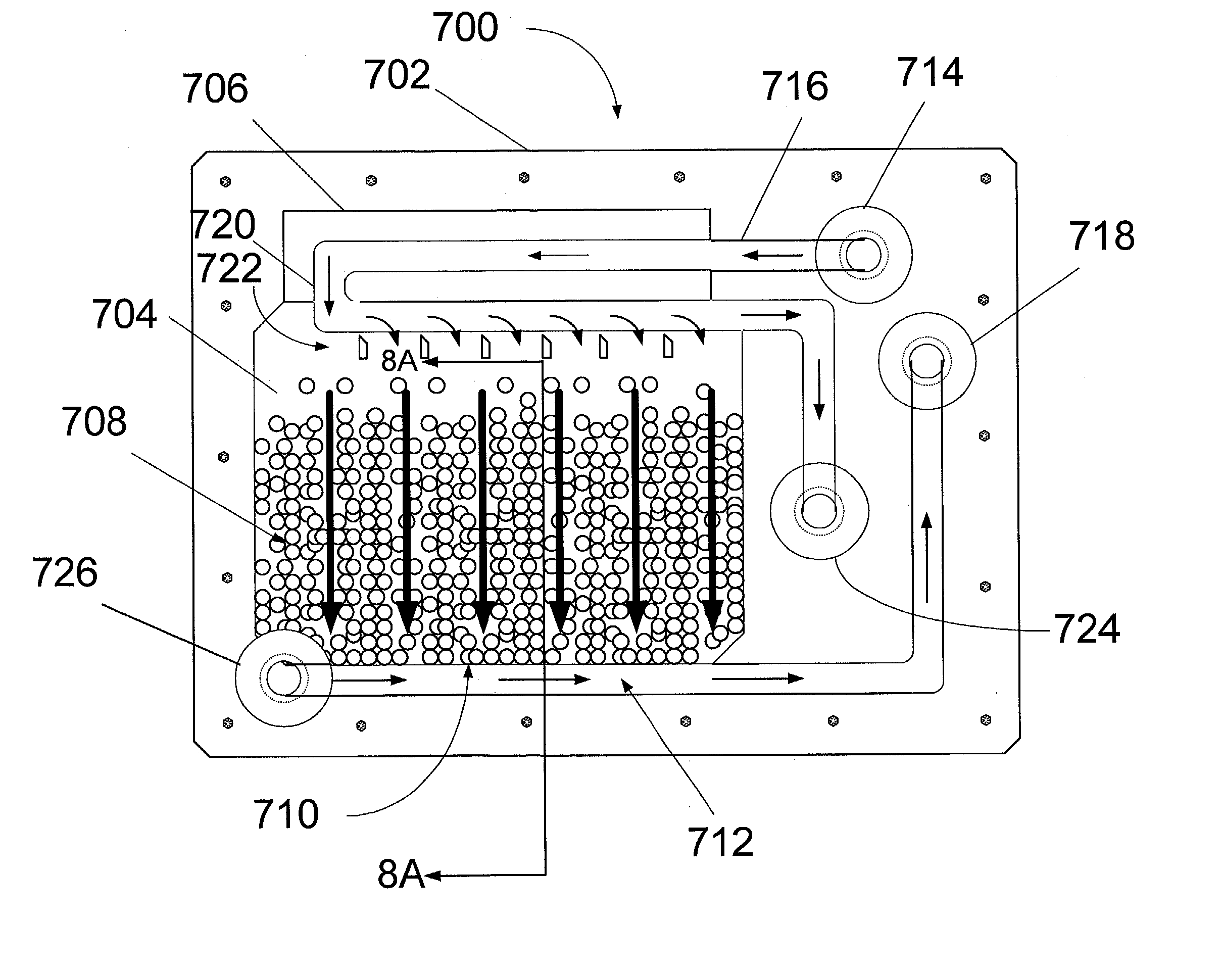
[0098] FIG. 7 is a front view of an embodiment of an individual cell 700 within the power source 102 of a metal-based fuel cell. A particulate anode 708 is maintained within a cell cavity 704 of the cell. Within the cell cavity 704, when the cell is in standby mode, the particulate anode may undergo electrochemical dissolution (although at a much slower rate than the discharge mode) due to corrosion.

[0099] A first flow path for a recirculating flow of the reaction solution is provided through the anode. This flow path may be activated in the standby mode of operation. In the particular embodiment illustrated in FIG. 7, the first flow path extends from top to bottom through the anode, and is represented by the vertical arrows within cell cavity 704. When the power source is in the standby mode, reaction solution (usually essentially free of metal particles, although it is possible to include them) enters the cell at orifice 714, proceeds along conduit 716, and is distributed into the...

second embodiment

[0112] A cross section 830 of cell 700 is illustrated in FIG. 8B. Again, this cross section represents the view 8B-8B of the cell 700 in FIG. 7. As with the previous embodiment, the cross-section is formed of a planar laminate arrangement of layers comprising from left to right cathode 806, separator 804, particulate anode 708, and current collector 808 embedded in a cell frame 802. The individual features of these layers have been previously described and need not be repeated except insofar as to discuss differences with the previous embodiment, which relate to the particle releaser 832 within the cell body 802.

[0113] In this embodiment, particle releaser 832 is formed of a screen, a top view of which is illustrated in FIG. 8C. The screen is in communication with the interior of the cell cavity through the openings 840 in the screen, which form a flow channel with conduit 712. As illustrated in FIG. 8C, each opening 840 has a long axis 844 and a short axis 842. The short axis 842 o...


PUM

PropertyMeasurementUnit
Poweraaaaaaaaaa
Concentrationaaaaaaaaaa
Areaaaaaaaaaaa

Abstract

A method of and system for flushing one or more cells or components thereof in a particle-based electrochemical power source is provided. Reaction solution is delivered to and withdrawn from the one or more cells when the electrochemical power source is in a standby mode of operation.

Description

RELATED APPLICATION(S)[0001] This application is related to U.S. patent application Ser. No. 10 / 060,965, entitled "RECIRCULATING ANODE", filed Oct. 19, 2001, and owned in common by the assignee hereof. U.S. Ser. No. 10 / 060,965 if hereby fully incorporated by reference herein as though set forth in full.[0002] This invention relates generally to the field of particle-based electrochemical power sources, and, more specifically, to techniques for flushing the cells thereofRELATED ART[0003] Particle-based electrochemical power sources, including without limitation metal-based fuel cells, are emerging as an attractive alternative to traditional energy sources. In metal-based fuel cells, when metal anodes within the cell cavities are exposed to an electrolysis agent such as hydroxide, an electrochemical reaction takes place whereby the metal releases electrons, and a reaction product is formed, typically one or more ions or oxides of the metal. Through this process, the metal anodes are g...

Claims


Application Information

Patent Timeline
IPC IPC(8): H01M4/02H01M8/04H01M8/22H01M12/06
CPCH01M4/02H01M8/04223Y02E60/50H01M12/065H01M2004/024H01M8/225H01M8/04186H01M8/04753H01M8/0258H01M8/241H01M8/04225
Inventor SMEDLEY, STUART I.NOVKOV, DONALD JAMESSMEDLEY, KENT I.ALSTADT, RAYMOND H.GROCHULSKI, FREDERICK R.
Owner METALLIC POWER INC
Why Eureka
Try Eureka