Head-up display
a display and head-up technology, applied in the field of head-up displays, can solve the problems of difficult molding of blocks, inability to meet the requirement of compact design, and increase the size of optical units
- Summary
- Abstract
- Description
- Claims
- Application Information
AI Technical Summary
Benefits of technology
Problems solved by technology
Method used
Image
Examples
first embodiment
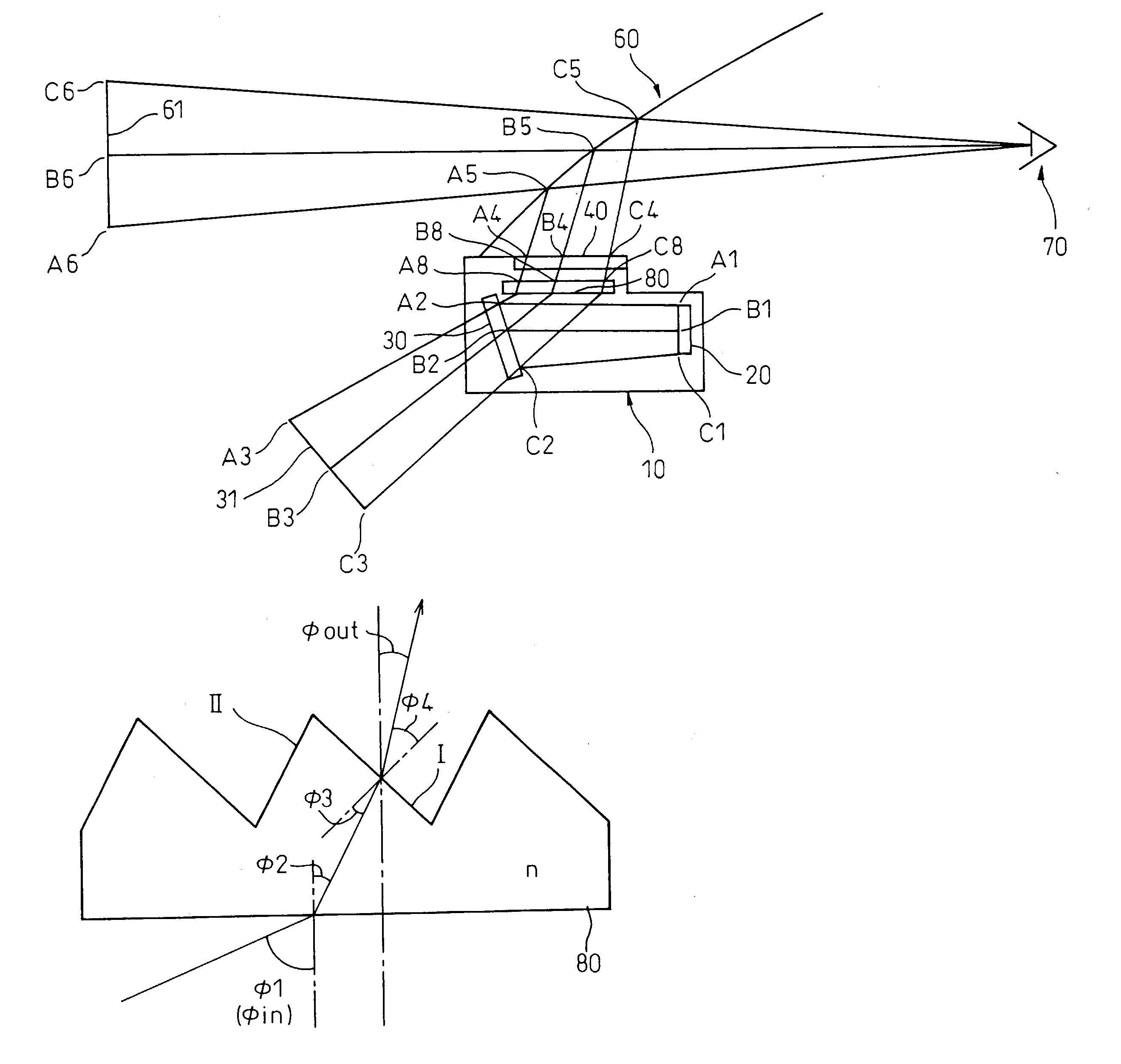
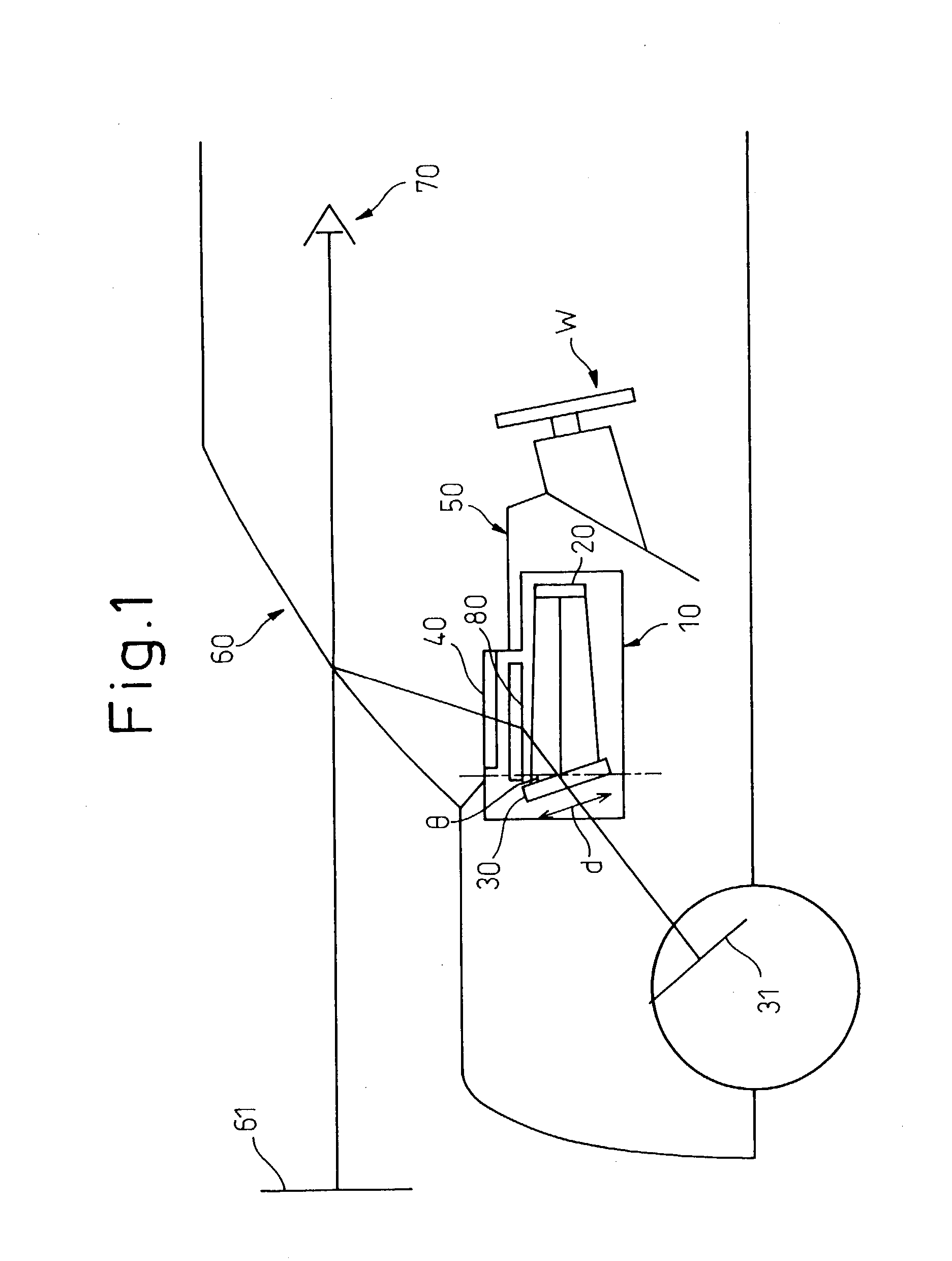
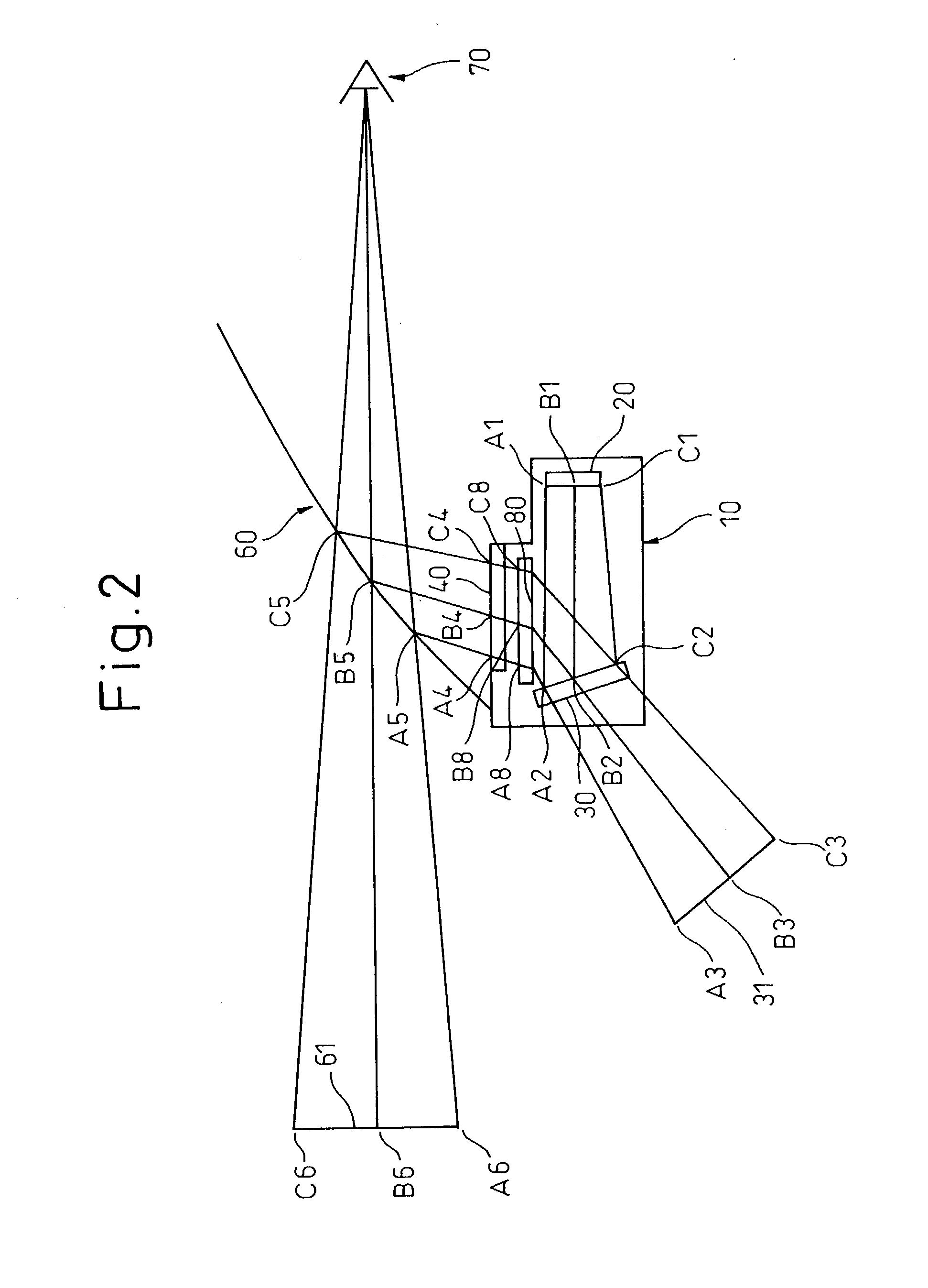
[0100] An example of the present invention will be described in conjunction with FIG. 1, FIG. 2, FIG. 8, and FIG. 9. FIG. 1 shows a case where a head-up display according to the present invention is adapted for a motorcar.
[0101] The head-up display includes an optical unit 10. The optical unit 10 includes a display device 20, a reflecting mirror (concave mirror) 30, and a prism sheet 80. A dustproof cover 40 made of, for example, a transparent resin is laid over an opening formed in the optical unit 10. The dustproof cover 40 may be mounted independently of the prism sheet 80 or the prism sheet 80 may be used as the dustproof cover 40.
[0102] Light emitted from the display device 20 is reflected from the concave mirror 30, and refracted through the prism sheet 80. The light is then incident on a windshield 60. When the incident light is reflected by the windshield 60, the windshield 60 presents display information (picture information) as a virtual image 61 formed ahead of a vehicle....
second example
[0115] The second example has the same advantages as the first example while employing a plurality of display devices. Referring to FIG. 10, the second example will be described below.
[0116] Referring to FIG. 10, an optical unit includes a display device 21 on which an image that emits light having a wavelength .lambda.1 is displayed and a display device 22 on which an image that emits light having a wavelength .lambda.2 is displayed. Furthermore, the optical unit includes a reflecting mirror 31 that reflects light emitted from the display device 21, and a half mirror 32 through which passes the light coming from the display device 21 and which reflects light coming from the display device 22. The display devices 21 and 22, reflecting mirror 31, and half mirror 32 are arranged so that a distance d between a virtual image of the display device 21 formed by the reflecting mirror 31 and a virtual image of the display device 22 formed by the half mirror 32 satisfy the equation (2) descr...
third example
[0121] The third example will be described in conjunction with FIG. 11 and FIG. 12. Light characteristics of the spectral distribution shown in FIG. 11 is emitted as light rays having different wavelengths from the display device 20 included in the first example. Referring to FIG. 11, light that is plotted as an acute curve in the center of FIG. 11 will be described as a typical example. The center wavelength of the light plotted as the acute curve is .lambda. and the half width of the acute curve is .DELTA..lambda.. The points on the curve determining the half width indicate wavelengths of .lambda.3 and .lambda.4 that are expressed as follows:
.lambda.3=.lambda.-.DELTA..lambda. / 2
.lambda.4=.lambda.+.DELTA..lambda. / 2
[0122] The light having the center wavelength .lambda. and the half width .DELTA..lambda. travels, as shown in FIG. 12, between light having the wavelength of .lambda.3 and light having the wavelength of .lambda.4 and reaches a view point.
[0123] Assuming that an angle of i...
PUM
 Abstract
Description
Claims
Application Information
 - R&D
- Intellectual Property
- Life Sciences
- Materials
- Tech Scout
- Unparalleled Data Quality
- Higher Quality Content
- 60% Fewer Hallucinations
Browse by: Latest US Patents, China's latest patents, Technical Efficacy Thesaurus, Application Domain, Technology Topic, Popular Technical Reports.
© 2025 PatSnap. All rights reserved.Legal|Privacy policy|Modern Slavery Act Transparency Statement|Sitemap|About US| Contact US: help@patsnap.com


