Light attenuation in defective pixel in organic EL panel

Active Publication Date: 2003-12-04
SANYO ELECTRIC CO LTD
View PDF7 Cites 39 Cited by
  • Summary
  • Abstract
  • Description
  • Claims
  • Application Information

AI Technical Summary

Problems solved by technology

A bright point is conspicuous, even when only one bright point is present among surrounding pixels displaying black, and the bright point is therefore viewed as a serious deficiency.
However, when a darkening process using a YAG laser is applied, the cathode is damaged and display of other pixels may be affected.
With such a structure, when the wiring to the TFT is severed using a YAG laser, the laser may reach the catho

Method used


Image

  • Light attenuation in defective pixel in organic EL panel
  • Light attenuation in defective pixel in organic EL panel
  • Light attenuation in defective pixel in organic EL panel

Examples


Embodiment Construction

[0030] Preferred embodiments of the present invention (hereinafter referred to simply as "embodiments") will now be described with reference to the drawings.

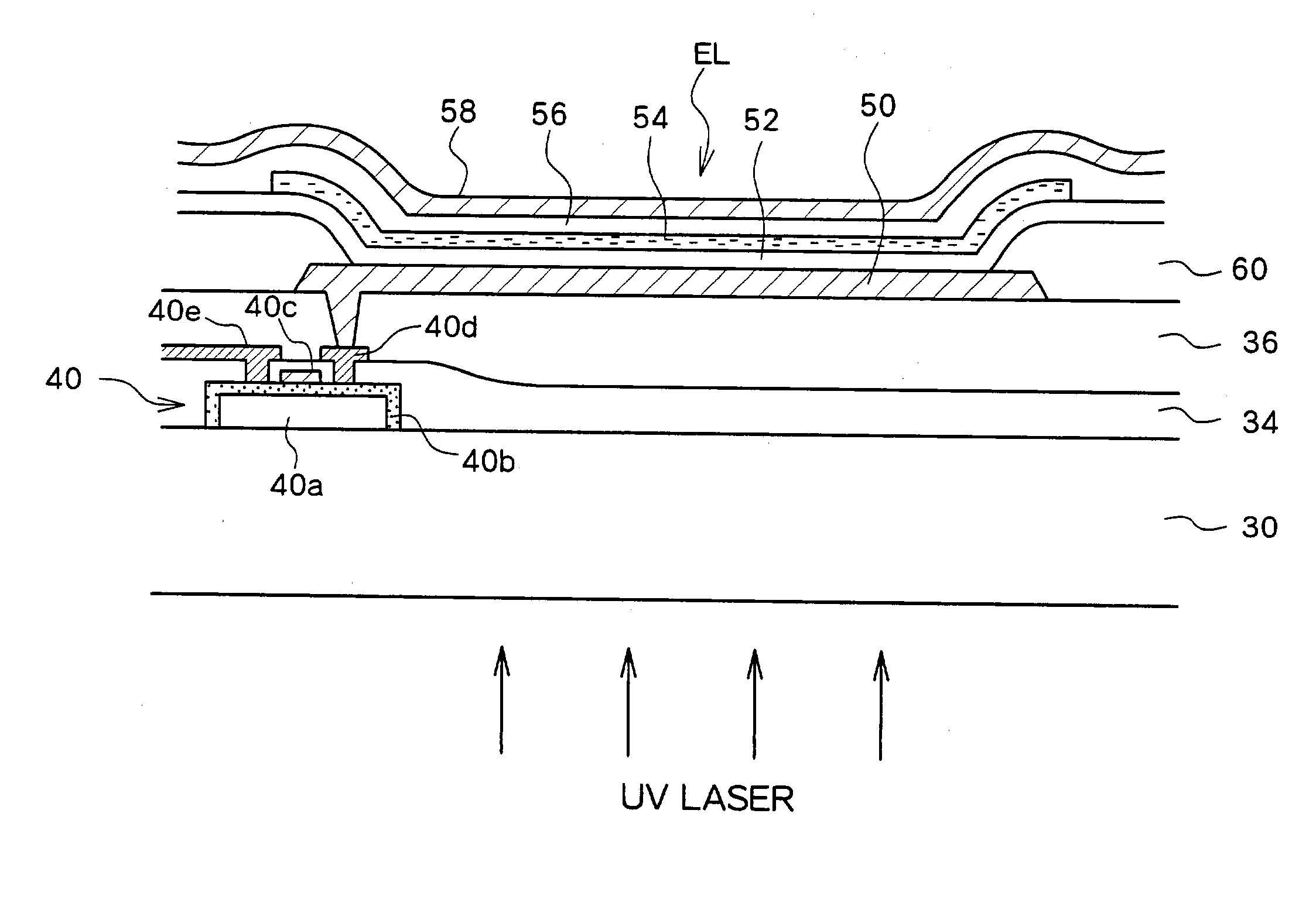
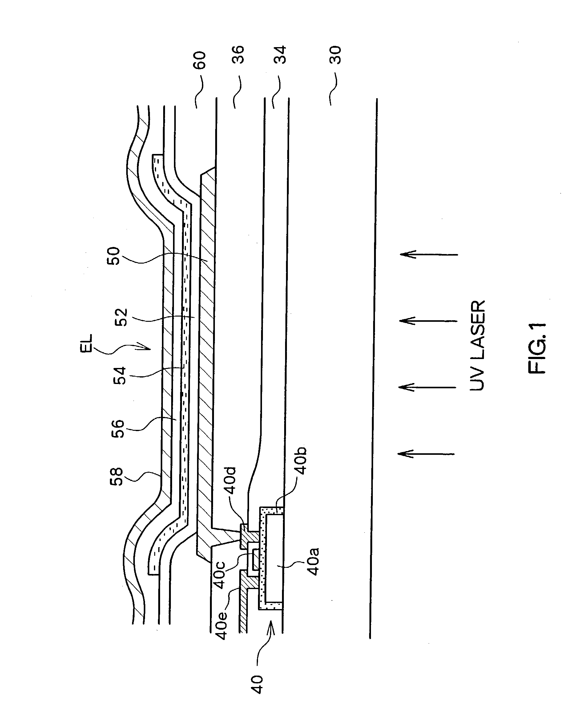
[0031] In an embodiment, a defective pixel is irradiated with laser light using an UV (short wavelength) laser, such as an excimer laser, as a light source. With the irradiation of laser light, the characteristics of the organic layer of the defective pixel is altered, the light emitting capability is degraded, and attenuation can be achieved. The alteration of the characteristics of the organic layer is considered as being caused by, for example, the thermal energy of the laser fusing each of a hole transport layer, an organic emissive layer, and an electron transport layer, resulting in a loss of the layered structure.

[0032] Specifically, the irradiated laser is not sufficiently intense to evaporate the irradiated layer, and a thermal alteration of the characteristics occurs in the organic layer absorbing the laser light in a ...


PUM

PropertyMeasurementUnit
Wavelengthaaaaaaaaaa
Currentaaaaaaaaaa
Lightaaaaaaaaaa

Abstract

An organic EL element of one pixel is selectively irradiated with laser light. With the laser irradiation, the functionality of the organic layer of the organic EL element is selectively degraded and the light emission capability is removed without damaging the cathode.

Description

[0001] 1. Field of the Invention[0002] The present invention relates to the repair of a defective pixel in an organic electroluminescence (referred to simply as "EL" hereinafter) panel.[0003] 2. Description of the Related Art[0004] Conventionally, organic EL display panels have been known as one type of flat display panel. Unlike liquid crystal display (LCD) panels, the organic EL display panels are self-emissive and commercialization of the organic EL display panels as clear and bright displays are highly expected.[0005] An organic EL display is constructed by arranging a plurality of pixels each having an organic EL element in a matrix form. As a method for driving the organic EL element, similar as in LCDs, a passive method and an active method are known. Of these, also similar to the case with LCDs, the active matrix method is more desirable. That is, an active matrix method in which a switching element is provided for each pixel and the display in each pixel is controlled by co...

Claims


Application Information

Patent Timeline
IPC IPC(8): G09G3/00H01L27/32H01L51/56
CPCG09G3/006Y10S428/917H01L2251/568H01L27/3244H10K59/12H10K71/861H05B33/10
Inventor NISHIKAWA, RYUJIJINNO, YUSHIOGAWA, TAKASHINAGATA, RYOUZOU
Owner SANYO ELECTRIC CO LTD
Why Eureka
Try Eureka