Fluid apparatus

a technology of fluid apparatus and compressor, which is applied in the direction of reciprocating piston engine, positive displacement liquid engine, etc., can solve the problems of reducing the reliability (durability) of the compressor, easy generation of noise, and large sound nois

Active Publication Date: 2003-12-04
DENSO CORP +1
View PDF5 Cites 14 Cited by
  • Summary
  • Abstract
  • Description
  • Claims
  • Application Information

AI Technical Summary

Benefits of technology

[0010] According to a first aspect of the present invention, a fluid apparatus includes a shaft disposed to be rotatable, a plurality of pistons disposed to be reciprocated, a housing for containing the shaft and having a plurality of cylinder bores in which the pistons are disposed, a rotary member rotatable integrally with the shaft, a swing member connected to a slant surface of the rotary member through a thrust bearing, and a swing support mechanism for supporting the swing member in capable of swinging. Further, the slant surface of the rotary member is disposed to slant with respect to a center axis of the shaft, and the swing member swings in accordance with rotation of the rotary member, for reciprocating the pistons. The swing support mechanism has a first rotation member rotatable about a first axial line that is vertical to the center axis of the shaft, a lock member connected to the first rotation member in order to restrict the first rotation member from rotating about the center axis of the shaft, and a second rotation member connected to the first rotation member to be rotatable about a second axis that is vertical to the center axis and crosses with the first axis. In the swing support mechanism, the second rotation member is connected to the swing member. In the fluid apparatus, the rotary member, the thrust bearing, the swing member and the second rotation member are disposed to construct a variable mechanism portion. Further, the swing support mechanism has a slant center around which the swing member swings, and the slant center is positioned substantially at a center of gravity of the variable mechanism portion. Accordingly, a slant moment for changing a slant angle of the swing member relative to the shaft is not structurally generated. Furthermore, a deviated dimension of the slant center from the center of the gravity of the variable mechanism portion is substantially zero. Therefore, it can prevent large vibration and large noise from being caused even when the shaft of the fluid apparatus operates at a high rotational speed. For example, the slant center is a crossing point between the first axis and the second axis.
[0012] According to a second aspect of the present invention, a fluid apparatus includes a shaft disposed to be rotatable, a plurality of pistons disposed to be reciprocated, a housing having a plurality of cylinder bores in which the pistons are disposed, a swash plate rotatable integrally with the shaft for reciprocating the pistons, and a shoe disposed at a radial outside portion of the swash plate to pinch the swash plate while slidably contacting the swash plate. In the fluid apparatus, the swash plate is disposed to slant with respect to a center axis of the shaft, and the swash plate and the pistons are connected through the shoe to be reciprocated. Further, the swash plate has a slant center about which the swash plate rotates while slanting, and the slant center substantially corresponds to a gravity center of the swash plate. Accordingly, even in this structure, a slant moment for changing the slant angle of the swash plate is not structurally caused. Therefore, the durability of the fluid apparatus can be improved while noise generated in the fluid apparatus can be effectively restricted.
[0013] Preferably, a balancer is provided for adjusting the slant center of the swash plate at a position substantially corresponding to the gravity center of the swash plate, regardless of a slant angle of the swash plate with respect to the center axis of the shaft. Therefore, the slant center can readily correspond to the gravity center of the swash plate. Generally, the gravity center of the swash plate is substantially on the center axis of the shaft.

Problems solved by technology

Therefore, when the fluid apparatus such as the compressor is operated, noise is readily generated due to gear collision between the bevel gears.
However, when the shaft rotates at a high rotational speed, the swing member swings and vibrates while rotating about the shaft.
The vibration from the swing member is transmitted to a housing of the compressor, thereby causing large sound noise.
Furthermore, at this time, the slide member and its support portion slide at a high rotational speed, thereby reducing reliability (durability) of the compressor.
As a result, in a variable displacement compressor for controlling its displacement by changing the slant angle of the swing member, the displacement (i.e., slant angle) becomes unstable, thereby inducing oscillation due to hunting.

Method used


Image

  • Fluid apparatus
  • Fluid apparatus
  • Fluid apparatus

Examples


first embodiment

[0034] (First Embodiment)

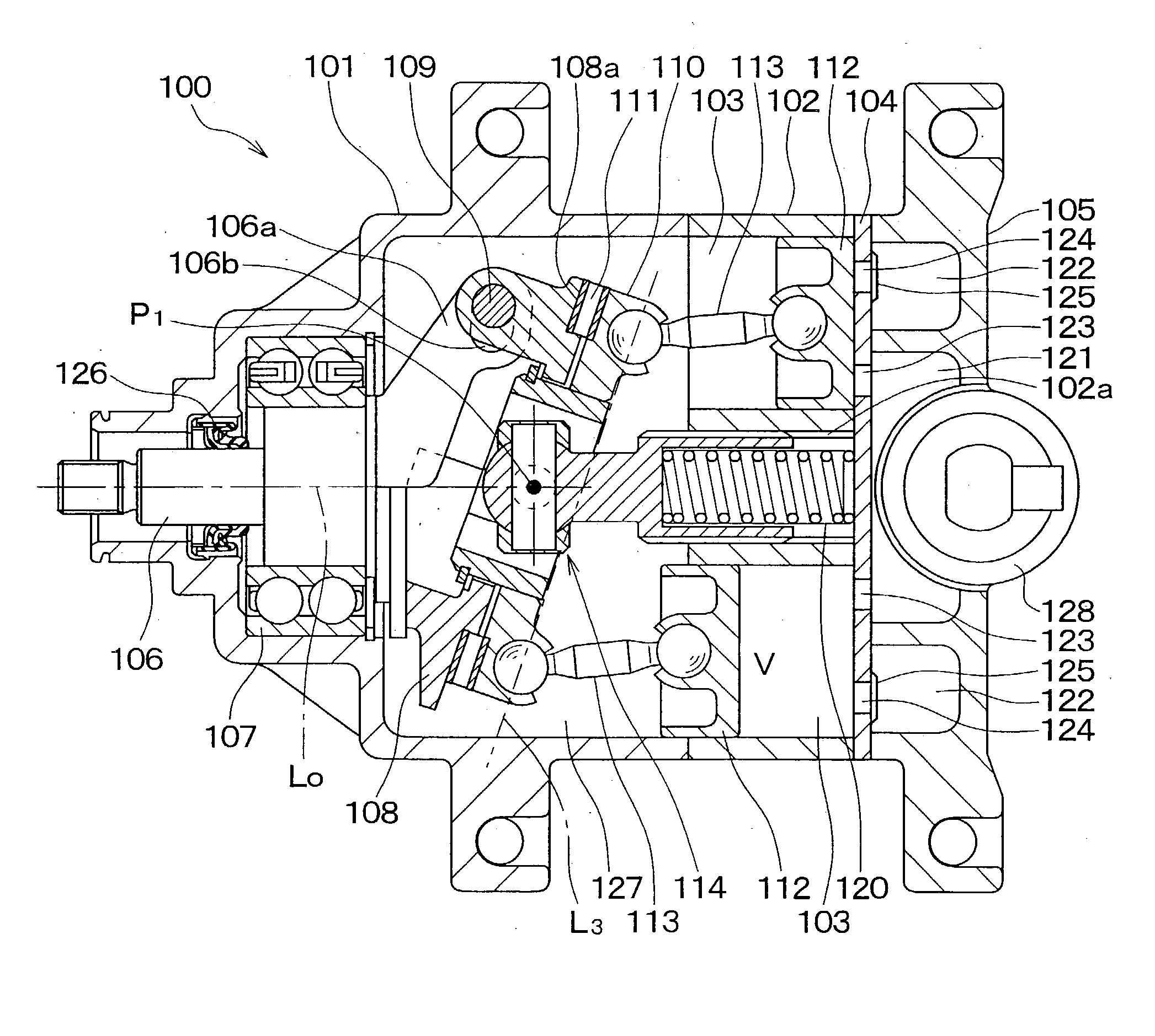
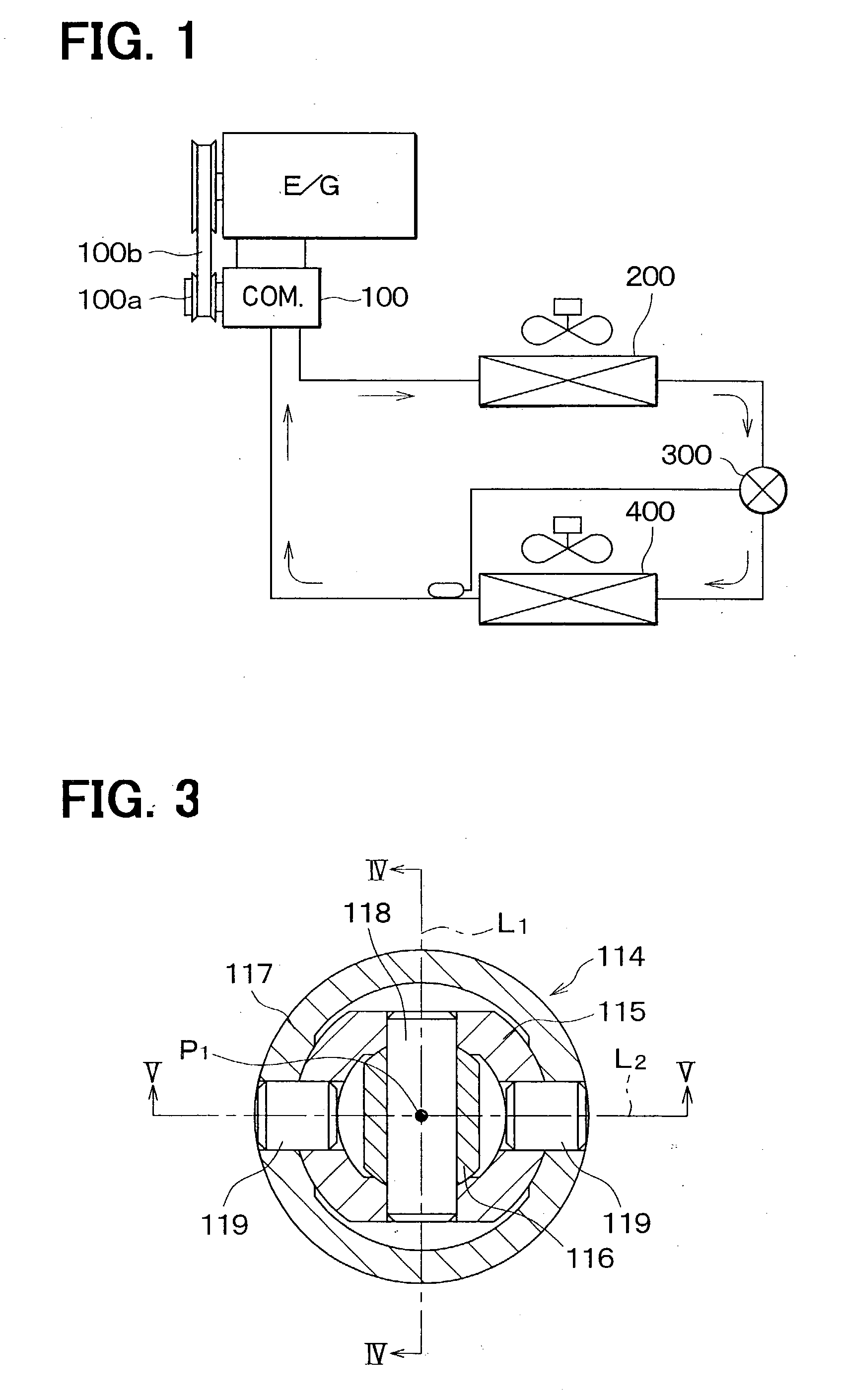
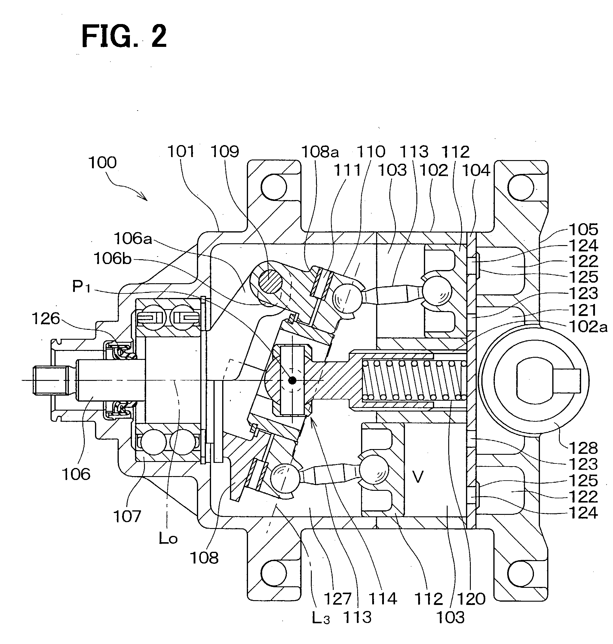
[0035] In the first embodiment, a fluid apparatus of the present invention is typically used for a wabble-type variable displacement compressor in a vapor compression refrigerant cycle for a vehicle shown in FIG. 1. The vapor compression refrigerant cycle with the compressor can be suitably used for a vehicle air conditioner. In FIG. 1, a compressor 100 sucks and compresses refrigerant by using motive power from an engine E / G that is a drive source for driving the vehicle. A part of the motive power from the engine E / G is transferred to the compressor. 100 through a pulley 100a and a V-belt 100b.

[0036] A condenser 200 is a radiator for condensing (cooling) refrigerant discharged from the compressor 100 by performing heat exchange between the discharged refrigerant from the compressor 100 and outside air. A decompression device 300 decompresses refrigerant flowing from the condenser 200. An evaporator 400 is a low-pressure heat exchanger for cooling air to be...

second embodiment

[0054] (Second Embodiment)

[0055] In the above-described first embodiment, the present invention is typically applied to the wabble-type variable displacement compressor. However, in the second embodiment, as shown in FIG. 10, the present invention is applied to a swash plate compressor. The swash plate compressor includes a swash plate 130, shoes 131, a balancer 132 and the like. The swash plate 130 rotates integrally with the shaft 106 while slanting with respect to the center axis Lo of the shaft 106, thereby reciprocating the pistons 112. Each of the shoes 131 pinches the swash plate 130 at a radial outside, and slidably contacts the swash plate 130. Further, the shoes 131 connect the swash plate 130 and the pistons 112 so that the pistons 112 are reciprocated. The balancer 132 is disposed to compensate centrifugal force applied to the swash plate 130. That is, in the swash plate compressor, as in the wabble-type variable displacement compressor, refrigerant pressure in a swash c...

third embodiment

[0059] (Third Embodiment)

[0060] The third embodiment is a modification of the above-described second embodiment. As shown in FIG. 11, in the third embodiment, a cylindrical collar 133 is attached to the shaft 106 to be slidable on the shaft 106, and a support pin 134 is provided on an outer peripheral surface of the cylindrical collar 133. The swash plate 130 is disposed to swing about the support pin 134, and is slanted relative to the center axis Lo of the shaft 106. Accordingly, in the third embodiment, a center of the support pin 134 is the slant center P1. In the third embodiment, the other parts are similar to those of the above-described second embodiment, and the advantages described in the second embodiment can be obtained.


PUM


Abstract

In a fluid apparatus used as a compressor, a swing support member is constructed of a hook-type adjustable joint, and supports a swing member in capable of swinging while restricting the swing member from rotating about a center axis of a shaft of the compressor. A variable mechanism portion is constructed of a rotary member rotatable around the shaft, the swing member and the like. A slant center around which the swing member swings is made to substantially correspond to a center of gravity of the variable mechanism portion. Therefore, a slant moment, for changing a slant angle of the swing member, is not structurally generated. Accordingly, even when the compressor operates, large vibration and large noise can be prevented, thereby improving durability of the compressor.

Description

[0001] This application is related to and claims priority from Japanese Patent Applications No. 2002-155162 filed on May 29, 2002, and No. 2003-82576 filed on Mar. 25, 2003, the contents of which are hereby incorporated by reference.[0002] 1. Field of the Invention[0003] The present invention relates to a fluid apparatus such as a wabble-type fluid apparatus and a swash-plate fluid apparatus, which is suitably used for a compressor in a vapor compression refrigerant cycle for a vehicle.[0004] 2. Description of Related Art[0005] A wabble-type fluid apparatus (e.g., swing-swash plate compressor) includes a rotary member, a swing member and a rotation lock mechanism. The rotary member has a swash surface slanted relative to a shaft of the fluid apparatus, and rotates integrally with the shaft. The swing member is connected to the swash surface through a thrust bearing, and swings with the rotation of the rotary member, thereby reciprocating a piston of the fluid apparatus. The rotation...

Claims


Application Information

Patent Timeline
Patent Type & Authority Applications(United States)
IPC IPC(8): F04B27/08F01B3/02F04B27/10
CPCF04B27/1072F04B27/1054
Inventor KAWANO, SHIGERUKAMIYA, HIROKAZUINOUE, MASAFUMIKAMIYA, SHIGERUMATSUDA, MIKIOINOUE, TAKASHI
Owner DENSO CORP
Why Eureka
Try Eureka