Portable campfire barrier system

a technology for containing systems and campfires, applied in the field of portable campfire containment systems, can solve the problems of loss of human life, damage to both property and natural resources, and does little to stop a fire from spreading

Inactive Publication Date: 2003-12-18
KLARICH EDWARD A +1
View PDF14 Cites 14 Cited by
  • Summary
  • Abstract
  • Description
  • Claims
  • Application Information

AI Technical Summary

Problems solved by technology

Too often though, unattended or carelessly constructed campfires become the source of a wildfire which has the potential to cause damage to both property and natural resources.
Further, wildfires can lead to the loss of human life, including the fire fighters combating the blaze.
Because of the devastating destruction that can result from a campfire, civil authorities often ban campfires in times of extreme fire danger in certain areas.
Unfortunately, a fire ring of rocks often does little to stop a fire from spreading due to, among other things, the gaps between the rocks and the overall low height of the rock ring.
While there is no doubt that fire pits are more effective than a fire ring of rocks, the permanent nature of a fire pit, the work involved to prepare a fire pit and relative high cost makes them unavailable at most camp sites, especially where the camp site is not in an established campground.
One disadvantage of the previously available devices is that disassembly results in multiple pieces having to be transported and stored.
It is also a significant disadvantage of rigid panels in that tedious assembly and disassembly is required.
Another disadvantage is that the size of the containment area cannot be finely adjusted in size due to the rigid nature of the sectional pieces.
Further, the multiple pieces of the described devices increases manufacturing costs.

Method used


Image

  • Portable campfire barrier system
  • Portable campfire barrier system
  • Portable campfire barrier system

Examples


Embodiment Construction

[0033] The features and advantages of the present invention will be set forth in the description which follows, and in part will be apparent from the description, or may be learned by the practice of the invention without undue experimentation. The features and advantages of the invention may be realized and obtained by means of the instruments and combinations particularly pointed out in the appended claims.

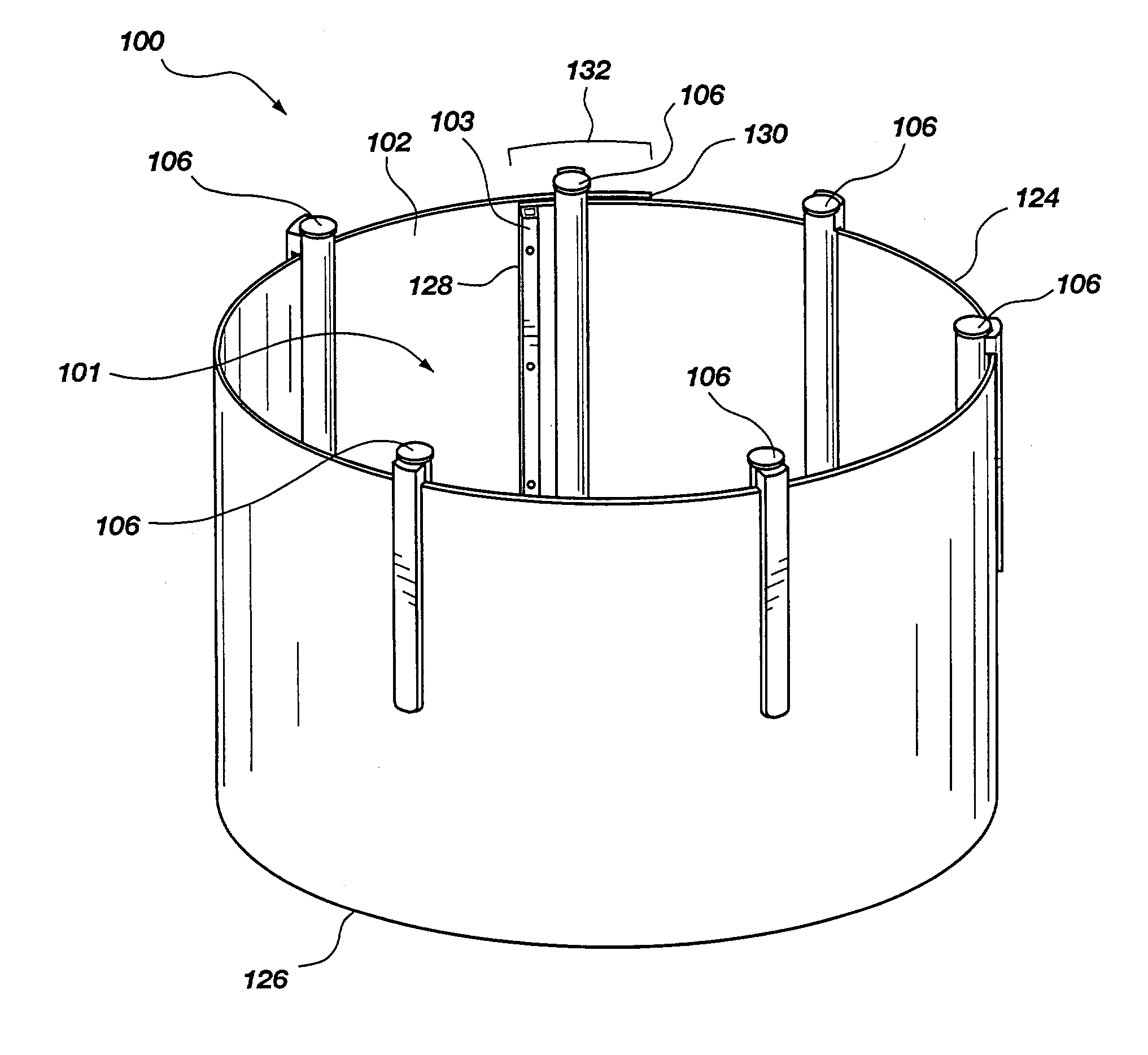
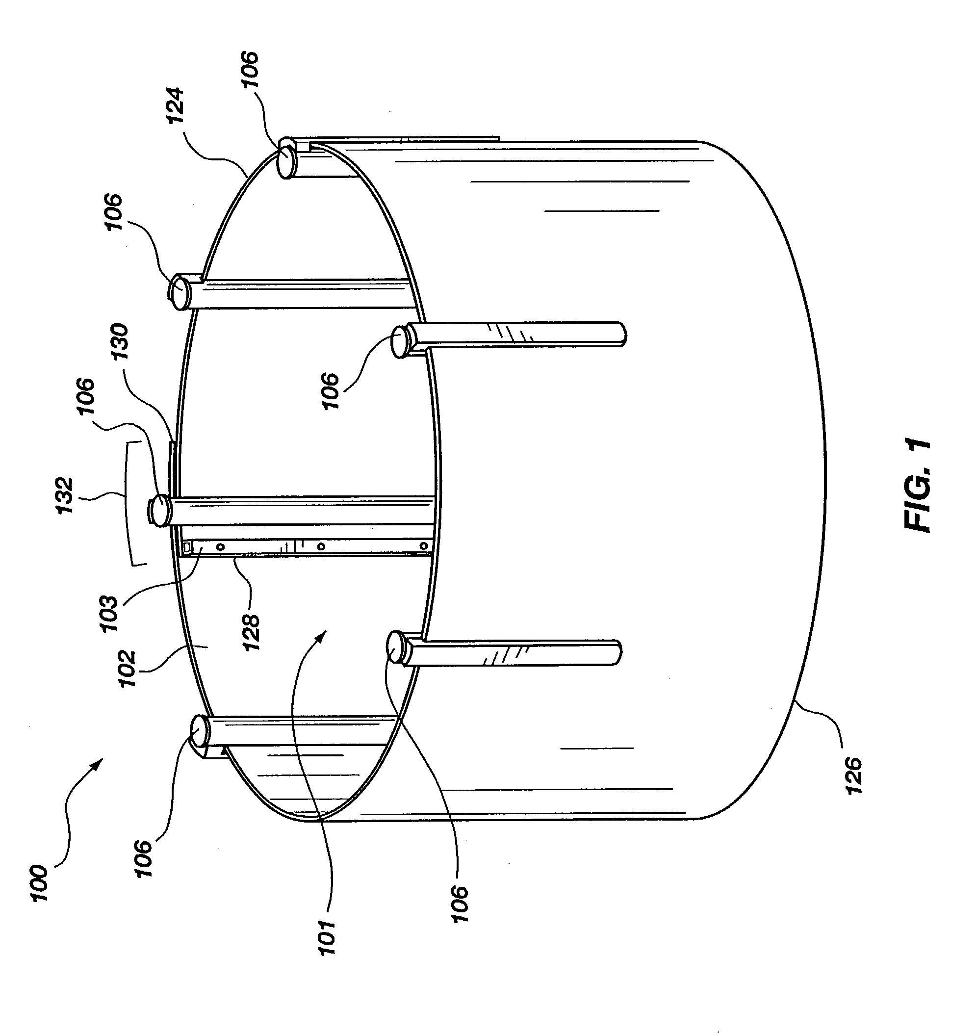
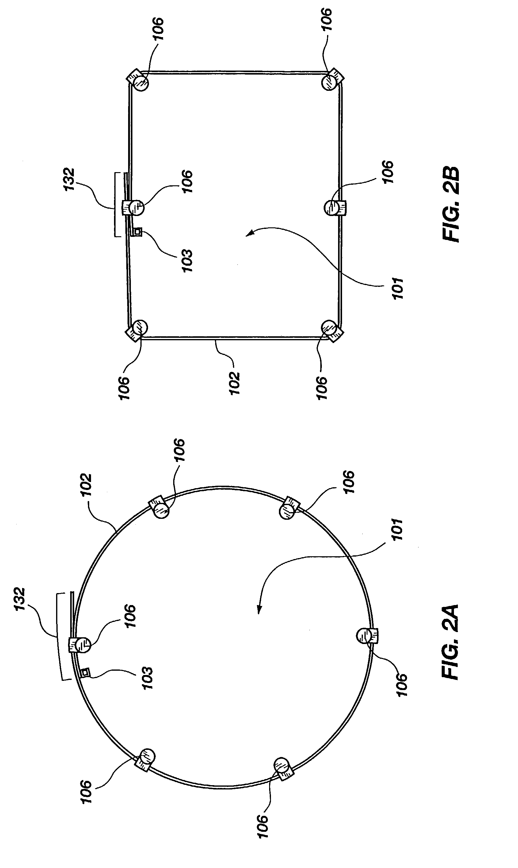
[0034] For the purposes of promoting an understanding of the principles in accordance with the invention, reference will now be made to the embodiments illustrated in the drawings and specific language will be used to describe the same. It will nevertheless be understood that no limitation of the scope of the invention is thereby intended. Any alterations and further modifications of the inventive features illustrated herein, and any additional applications of the principles of the invention as illustrated herein, which would normally occur to one skilled in the relevant art and...


PUM


Abstract

A portable campfire barrier system for preventing the spread of a campfire beyond an established perimeter that includes a one-piece containment wall secured in a ready-to-use configuration by a plurality of support members. When not deployed in the ready-to-use configuration, the containment wall can be collapsed for facilitating both storage and transport due to its ductile nature. The containment wall is of sufficient height to avert the campfire from igniting fuel beyond the containment area but still allow for the pleasant enjoyment of the campfire. In one form, the support members are adapted to engage the containment wall with clip members in order to maintain the wall in the ready-to-use configuration. A band fastened to one end of the containment wall further assists in maintaining the wall in the ready-to-use configuration. The support members are further adapted to be driven into the ground thereby providing additional stability. Optionally, a grill can be positioned on or over the containment wall to receive heat from the campfire.

Description

[0001] This application claims the benefit of U.S. Provisional Application No. 60 / 388,083 filed on Jun. 12, 2002, which is incorporated herein in its entirety to the extent that said U.S. Provisional Application is not inconsistent with the disclosure provided herein.[0002] Not Applicable.[0003] 1. The Field of the Invention.[0004] The present invention relates generally to campfire containment, and more particularly, but not necessarily entirely, to a portable campfire containment system.[0005] 2. Description of Background Art.[0006] Sitting around a campfire is a favorite pastime for many people. Too often though, unattended or carelessly constructed campfires become the source of a wildfire which has the potential to cause damage to both property and natural resources. Further, wildfires can lead to the loss of human life, including the fire fighters combating the blaze. Because of the devastating destruction that can result from a campfire, civil authorities often ban campfires ...

Claims


Application Information

Patent Timeline
Patent Type & Authority Applications(United States)
IPC IPC(8): F24C15/36
CPCF24C15/36
Inventor KLARICH, EDWARD A.KLARICH, KEVIN E.
Owner KLARICH EDWARD A
Why Eureka
Try Eureka