System and elements for managing therapeutic gas administration to a spontaneously breathing non-ventilated patient

a technology for managing systems and elements, applied in the direction of valve details, respiratory masks, medical devices, etc., can solve the problems of large volume of air and/or oxygen to be supplied, increase adverse bioeffects, and reduce the effect of gas waste, small cannula latency, and small outlet lumen latency

Inactive Publication Date: 2003-12-30
ADVANCED INHILATION THERAPIES AIT LTD
View PDF25 Cites 213 Cited by
  • Summary
  • Abstract
  • Description
  • Claims
  • Application Information

AI Technical Summary

Benefits of technology

It is another object of the present invention to manage NO delivery to a spontaneously breathing, non-ventilated patient such that concentrated NO is as low as reasonably possible while delivering the desired amount of NO to the distal portions of the patient's lungs.
The equalizing valve of the present invention satisfies the above-stated objects. The valve has inlet sealing surfaces within the valve fitting that engages a supply fitting of a source of pressurized gas at the closest possible location to the supply inlet. The remaining volume of the inlet is reduced by substantially filling that volume with a pin, leaving a thin annulus for gas to pass into the system. This geometry helps preserve the downstream gas purity and will significantly reduce the required amount of purge gas.

Problems solved by technology

However, as will be discussed, each of the known systems and devices has drawbacks.
This system has the disadvantage of wasting gas since not all therapeutic gas is inhaled by the patient.
In addition, large volumes of air and / or oxygen must be supplied to dilute / mix the therapeutic gas.
This may increase adverse bioeffects and the possibility of undesirable reaction products from the therapeutic gas.
The mask also makes eating and talking difficult and is also aesthetically unappealing.
Still further, a mask may make some patients nervous and cause anxiety by making them feel confined.
This system and method has the disadvantage that it does not dilute the therapeutic gas, so a high concentration source cannot be used.
This could have adverse bioeffects.
This method does not have the flexibility of varying the concentration of the therapeutic gas at various times during inspiration.
While overcoming many disadvantages associated with a mask, this method also has disadvantages as practiced in the known art.
This may have adverse bioeffects.
If lower concentration gas is used, the source lifetime / size advantages of a high concentration source are lost.
Also, the final dilution concentration in the respiratory tract is limited.
This method has all the disadvantages discussed above, except that it allows a higher diluted concentration to be delivered to the respiratory tract without having a hypoxic mixture.
This has the accompanying disadvantage of requiring a supplemental oxygen source.
This method has the disadvantage of requiring a diluent gas source.
If supplemental oxygen therapy is desired, oxygen or enriched air may be used as the diluent gas, but it is more difficult to control the oxygen concentration reaching the respiratory tract because a minimum diluent gas flow is required to dilute the therapeutic gas to a safe concentration in the cannula.
It is further diluted in the respiratory tract by entrained air from the room, This method has the disadvantage of requiring a diluent gas source.
If supplemental oxygen is required, a source of air and a source of oxygen will be required or it will be difficult to control the oxygen concentration reaching the respiratory tract.
This method has the disadvantage that the therapeutic gas is not diluted prior to entering the respiratory tract.
This may have adverse bioeffects.
If lower concentration gas is used, the source lifetime / size advantages of a high concentration source are lost.
Also, the final diluted concentration in the respiratory tract is limited.
The transtracheal catheter is invasive, which is often undesirable.
It is noted that not every patient has the same breathing pattern as other patients so a pulse configuration and time that is suitable for one patient may not be completely efficient for another patient.
For example, known cannulas do not have means for efficiently controlling mixing of gases and do not have a gas mixing area that is most efficient or most efficiently located.
More specifically, many known cannulas do not provide a location for mixing gases that is remote from a patient's nares.
However, since known cannulas do not have such an element, they have disadvantages.
Further, many known cannulas cannot be used in a system that can precisely detect breathing patterns of a patient and cannot be used to precisely and accurately control dosage, concentration and flow rates of the gases.
However, a check valve system may have drawbacks if used in certain circumstances.
For example, when a pressurized source is exchanged, there exists the possibility that air will be trapped within the volume of the system plumbing that is exposed to air during the exchange.
Any trapped air will degrade the quality of the high purity gases contained within the remainder of the system when intervening valves are opened.
A flow direction check valve is not able to achieve all of these goals.
However, for purging to be effective, the dead space must be substantially swept out during periods of gas flow.
Furthermore, purging requirements are strongly dependent on the relative size of the contaminated volumes.
Purging is often complicated in many situations due to possible toxic effects of the therapeutic gases; and the high cost of medical grade gases.
If, subsequent to this, a supply is attached that is at a lower pressure than the "checked" pressure, the system will not be able to detect the connection.

Method used


Image

  • System and elements for managing therapeutic gas administration to a spontaneously breathing non-ventilated patient
  • System and elements for managing therapeutic gas administration to a spontaneously breathing non-ventilated patient
  • System and elements for managing therapeutic gas administration to a spontaneously breathing non-ventilated patient

Examples


Embodiment Construction

Other objects, features and advantages of the invention will become apparent from a consideration of the following detailed description and the accompanying drawings.

Overall System

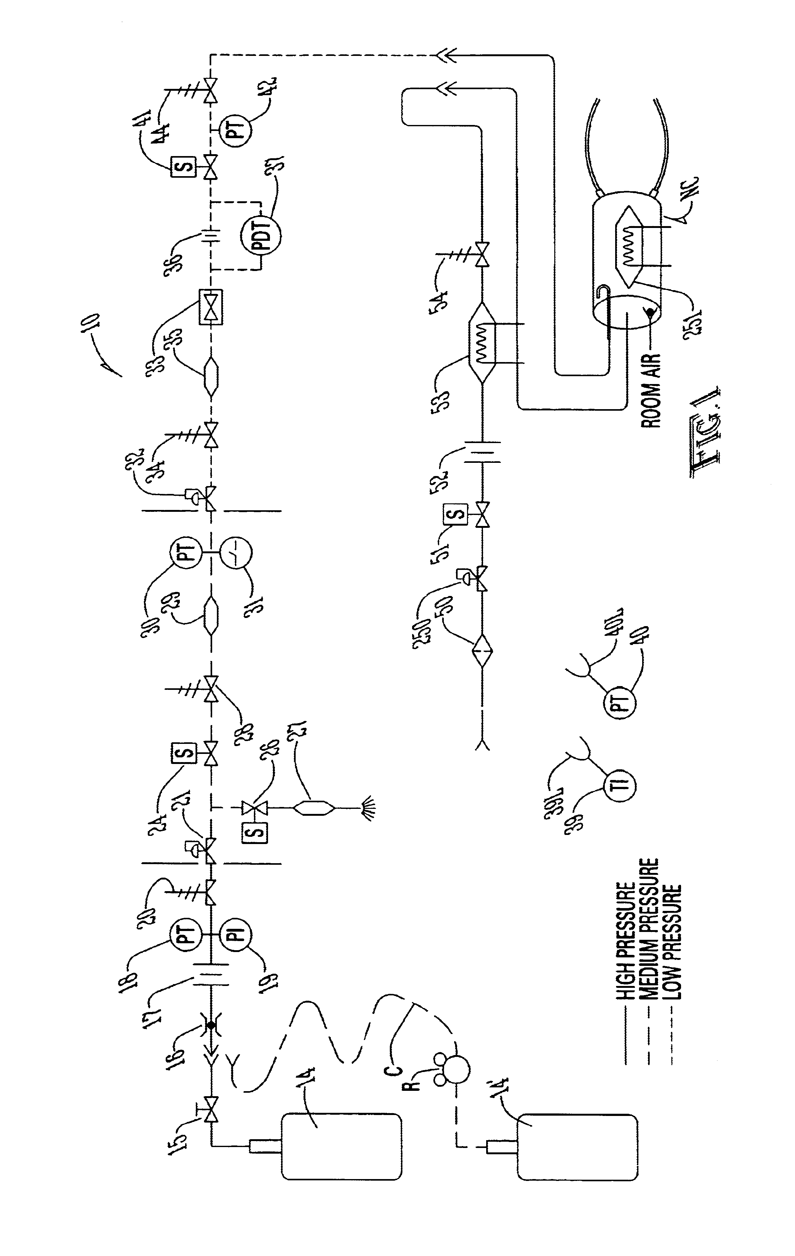
Referring first to FIG. 1, a description of the overall system for administering therapeutic gas to a spontaneously breathing, non-ventilated patient will be described. It is noted that for reference, unless otherwise stated, the terms "upstream" and "downstream" will refer to a flow direction of gas from a source toward a patient. Other terms such as "inlet" and "outlet" will refer to the same flow direction. The overall system 10 is shown schematically and includes a source of first compressed gas 14 which is fluidically connected via a valve 15 and a pressure equalization valve 16 to a flow restrictor 17. Alternatively, a large source of gas 14' can be connected via a pressure regulator R which reduces the pressure and a flow conduit C to the inlet of the system. During normal operation of system 10, wh...


PUM


Abstract

A system controls and manages administration of a therapeutic gas, such as NO, O2, or the like, to a spontaneously breathing, non-ventilated patient such that concentrated NO is as low as reasonably possible while delivering the desired amount of NO to the distal portions of the lungs. The system includes an entrainment cell that provides remote, turbulent mixing with low temporal latency and can be used with a nasal cannula or a mask. The entrainment cell uses room air to dilute the therapeutic gas; however, supplementary gases can also be used. A baffle can be included to promote mixing and a flow sensor can also be used if desired. Multiple ports can be included in the entrainment cell. An equalizing valve is also disclosed.

Description

The present invention relates to the general art of surgery, and to the particular field of introducing material to a patient for therapeutic or diagnostic purposes, most specifically, the invention relates to NO therapy.The use of therapeutic gases to treat a human or animal patient has been known in the art for many years. A number of different gases may be added to a respiratory gas that is inhaled by a spontaneously breathing, non-ventilated patient. These gases may be used to achieve some therapeutic effect, service a diagnostic function or have some other desirable purpose. Such gases will be referred to herein as "therapeutic gases." One skilled in the delivery of therapeutic gas will understand that the disclosure can be used to teach either human or animal patients. Accordingly, no limitation to human is intended by references to patient in this disclosure.One therapeutic gas is nitric oxide (NO), which is administered by inhalation in low concentrations to treat primary or...

Claims


Application Information

Patent Timeline
Patent Type & Authority Patents(United States)
IPC IPC(8): A61M16/00A61M16/20A61M16/06
CPCA61M16/00A61M16/0816A61M16/208A61M16/0677A61M2202/0275A61M2205/6027A61M2205/8206A61M2205/8237A61M2205/6018A61M16/0051A61M2016/0027A61M2016/0039A61M2016/0042A61M16/203A61M16/209A61M16/024Y10T137/7808
Inventor FIGLEY, CURTIS B.HUNT, DARIN W.MILLER, CHRISTOPHER C.
Owner ADVANCED INHILATION THERAPIES AIT LTD
Why Eureka
Try Eureka