
Non-snagging protective guide for fish tapes

a protective guide and fish tape technology, applied in the field of fish tapes, can solve the problems of fish tape and the combination of objects being fished, often jamming or hanging up, damage to the object being fished, and to any item within the cavity,

Inactive Publication Date: 2004-01-15
HAZEL DANNY G
View PDF9 Cites 14 Cited by
  • Summary
  • Abstract
  • Description
  • Claims
  • Application Information

AI Technical Summary

Benefits of technology

[0021] Another advantage of the invention is that it enables a fish tape to function as intended without getting caught on obstructions, corners, edges, or other such protrusions.
[0031] Another advantage of the invention is that with the protective guide, objects can be "fished" through smaller openings, as the opening need only be slightly larger than the object being "fished."

Problems solved by technology

A common problem encountered when using fish tapes is that the fish tape and object being fished combination often gets jammed or hung up while being pulled through the conduit or cavity.
Jamming can result in damage to the object being fished, as well as, to any item within the cavity.
Also, the leading end of the fish tape frequently gets stuck while passing through the opening in the conduit or passageway, bends in the cavity, or snags on obstacles within the cavity or conduit.
Repeatedly pushing and pulling by one person can sometimes free up the wire so it slides through the opening, or past the obstruction, but this requires several attempts and sometimes is not successful.
This connection zone still is prone to snagging.
This device has a very limited use in that it is adapted for use solely with ribbon type of cable.
One disadvantage with the Holden fish leader is that the coupler is a fixed and rigid shape in order to accommodate the shape of a conventional computer cable connector.
Thus, as with the others, the Holden fish leader will not prevent snags.

Method used


Image

  • Non-snagging protective guide for fish tapes
  • Non-snagging protective guide for fish tapes
  • Non-snagging protective guide for fish tapes

Examples


Embodiment Construction

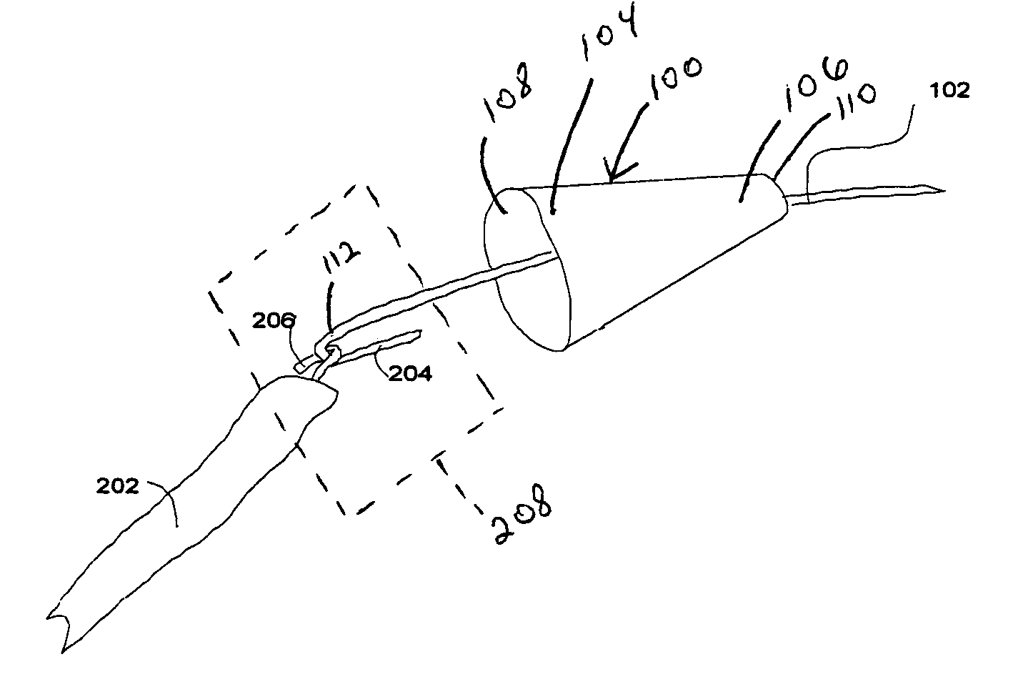
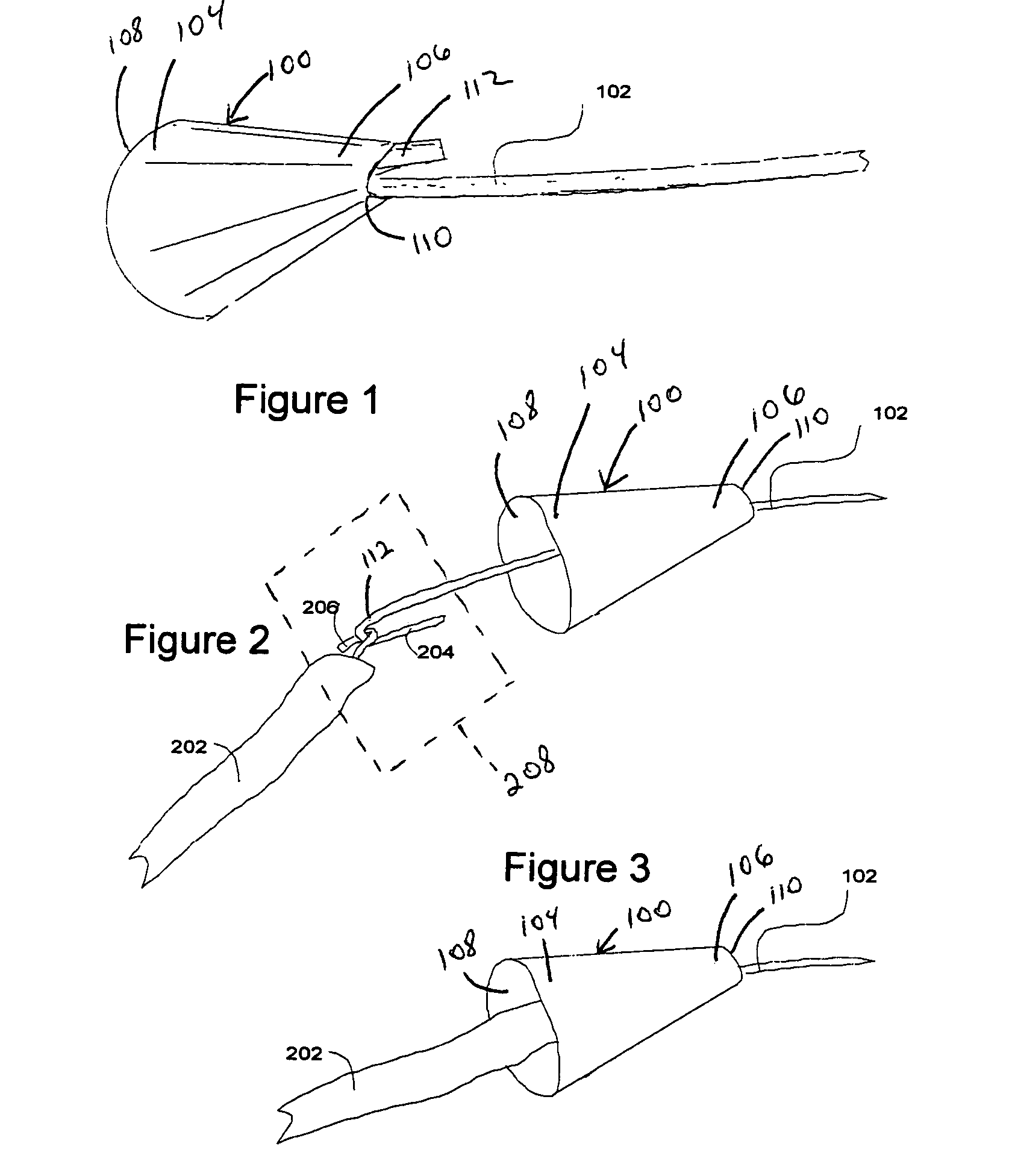
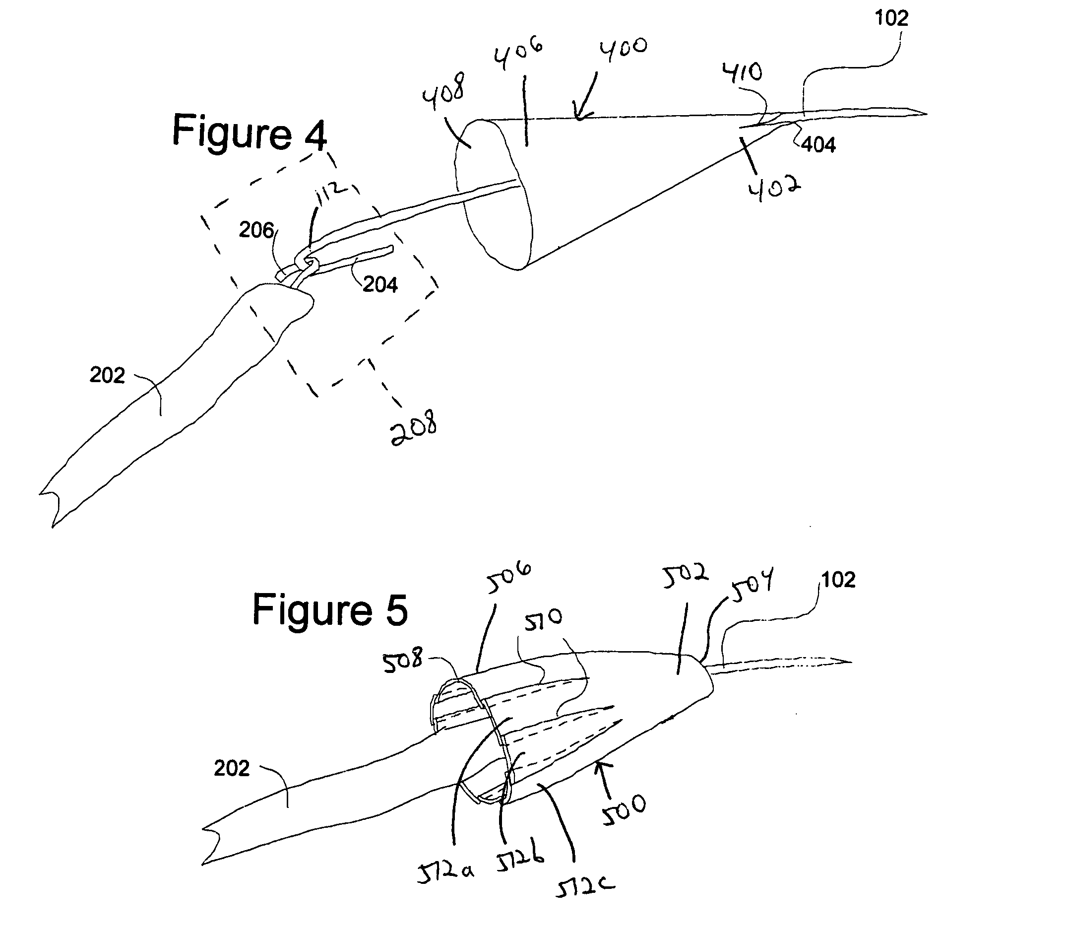
[0038] Referring to the figures, the present invention is a protective guide 100 having a means for encasing a connection zone 208 formed where an end of a fish tape 102 is joined to an object 202 that is to be pulled, or "fished," through an opening. Non-limiting examples of an object 202 to be fished through an opening include cables and wires. The protective guide 100 creates a smooth transition from the fish tape 102 to the object 202, thereby preventing the connection zone 208 from snagging on obstacles within an opening or on the opening itself. "Connection zone" 208 is defined as the region where an end of fish tape 102 is joined to an object 202 to be fished through an opening. More specifically, the connection zone 208 is the region (i) where a transition is made from a fish tape 102 to an object 202 being fished, and (ii) having projections, protrusion, or edges--resulting from the joining of the fish tape 102 to the object 202 to be fished--likely to snag in an opening or...


PUM


Abstract

A means for encasing a connection zone formed by joining an end of a fish tape to an object, e.g., a cable or wire, to be fished through an opening and / or conduit. The encasing means preferably is a protective guide being a hollow tube generally cone or funnel shaped for encasing the connection zone. By encasing the connection zone, the protective guide creates a smooth transition from the relatively small fish tape wire to the relatively large object being fished. The protective guide reduces the likelihood of the connection zone getting snagged on an opening or conduit through which a wire or cable is to be fished. The protective guide can have one or more lateral slits through its outer surface and extending from a second larger end toward a first smaller end for decreasing the outside diameter of the protective guide upon the exertion of pressure against the protective guide. The lateral slits allow the protective guide to adapt to external inward pressure applied, for example, by the walls of a narrow cavity or opening.

Description

[0001] This application claims the benefit of U.S. application Ser. No. 60 / 392,780 filed Jul. 1, 2002 and U.S. application Ser. No. 60 / 412,128, filed Sep. 19. 2002.[0002] 1. Field of the Invention[0003] The present invention is directed generally to fish tapes and all means for fishing an object through blind or inaccessible cavities, and more specifically, to a non-snagging protective guide for use with fishing an object.[0004] 2. Related Art[0005] A fish tape most commonly is used to pull electrical wire or cable through conduits, tight passageways, and blind and inaccessible openings or cavities. The fish tape may include a wire which is pushed through a small opening in one end of the cavity and out the opening at the other end. Then, the electrical wire. cable, or other linear object to be fished through the opening, is attached to the end of the fish tape. The fish tape, with the attached object, is then pulled back through the cavity and out the first opening. Once the object...

Claims


Application Information

Patent Timeline
IPC IPC(8): B65HB65H59/00B66F3/00
CPCH02G1/081
Inventor HAZEL, DANNY G.
Owner HAZEL DANNY G
Learn More