
Threading device

A threader and threading technology, which is applied in the field of threaders, can solve the problems of low threading efficiency, lower threading work efficiency, and slow traction speed, etc., and achieve the effects of speeding up threading efficiency, speeding up movement, and improving work efficiency

Active Publication Date: 2017-10-24
左永喜
View PDF6 Cites 2 Cited by
  • Summary
  • Abstract
  • Description
  • Claims
  • Application Information

AI Technical Summary

Problems solved by technology

[0003] With the continuous advancement of science and technology, the threader made of plastic material and glass fiber reinforced plastic has replaced the above-mentioned threader made of long steel wire. The threader includes a threading probe, The threading body and the hanging ring are affected by the structure of the threader itself, and the pulling speed of the threader itself is slow, resulting in low threading efficiency of the threader and reducing the working efficiency of the threading work

Method used


Image

  • Threading device
  • Threading device
  • Threading device

Examples


Embodiment

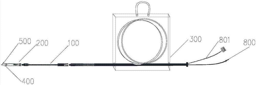
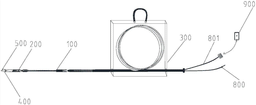
[0049] According to one aspect of the present invention, as figure 1 As shown, a threader is provided, including a threader main body 100, a threading probe 200, a hanging wire assembly 300, and a plurality of rolling assemblies 400 rollingly connected with the pipeline;

[0050] The threading probe 200 is arranged at one end of the threader main body 100, and the thread hanging assembly 300 is arranged at the other end of the threader main body 100;

[0051] Each rolling assembly 400 is installed on the threading probe 200 so that the threading probe 200 is in rolling connection with the pipeline.

[0052] According to the threader of the present invention, during the threading process of the threader in the pipeline, since the rolling assembly 400 on the threading probe 200 is rollingly connected with the pipeline, the rolling assembly 400 can roll in the pipeline, and the rolling assembly 400 The rolling of the threading probe 200 can speed up the movement of the threading...

Embodiment approach

[0063] According to an embodiment of the threader of the present invention, the cleaning component 500 is a scraper 501 and a hook 502; the tip 201 is provided with an opening 503 compatible with the scraper 501 and a depression 504 compatible with the hook 502;

[0064] One end of the scraper 501 is equipped with a hook 502;

[0065] The other end of the scraper 501 is rotatably connected to the tip 201 so that the scraper 501 and the hook 502 have a first station and a second station relative to the tip 201;

[0066] When the scraper 501 and the hook 502 are in the first position relative to the tip 201, the scraper 501 covers the opening 503, and the hook 502 is hooked at the recess 504; when the scraper 501 and the hook 502 are relative to the tip When 201 is in the second position, the scraper 501 and the hook 502 form an angle with respect to the tip 201 .

[0067] According to the threader of the present invention, the main function of the cleaning assembly 500 is to d...


PUM


Abstract

The invention discloses a threading device, and relates to the technical field of threading tools. According to the threading device, the threading device comprises a threading device body, a threading probe, a thread hanging component and multiple rolling components which are connected with a pipeline in a rolling way. The threading probe is arranged on one end of the threading device body. The thread hanging component is arranged on the other end of the threading device body. Each rolling component is installed on the threading probe so that the threading probe is enabled to be connected with the pipeline in a rolling way. According to the threading device, the threading device is high in threading efficiency so that the work efficiency of the threading work can be enhanced.

Description

technical field [0001] The invention relates to the technical field, in particular to a threader. Background technique [0002] With the continuous development of my country's economic construction, the construction industry has developed rapidly, and many electrical equipment such as power supply line pipelines, communication line pipelines, switch socket panels, etc. The wiring of the communication line pipeline and the switch socket panel etc. adopts the traditional plastic pipe wiring. The method is to pre-bury the plastic pipeline in the above-mentioned power supply line pipeline, communication line pipeline and switch socket panel, etc., and then put various wires through them. In the pre-buried plastic pipeline, the operation process is to hook the wire that needs to be inserted on one end of a long steel wire, and pull the wire hooked at the end of the steel wire into the plastic hose through the steel wire; [0003] With the continuous advancement of science and tech...

Claims


Application Information

Patent Timeline
IPC IPC(8): H02G1/08
CPCH02G1/088
Inventor 左永喜
Owner 左永喜
Learn More