Wireless bar code symbol reading system capable of automatically collecting and storing symbol character data when hand-supportable unit is operated outside of its RF data communication range, and automatically transmitting stored symbol character data when the hand-supportable unit is operated within its RF data communication range

a bar code and reading system technology, applied in the field of automatic laser scanning bar code symbol reading system, can solve the problems of reducing worker productivity, difficult to achieve in practice, waste of valuable time and resources of users, etc., and achieve the effect of avoiding barcode loss

Inactive Publication Date: 2004-01-29
METROLOGIC INSTR
View PDF99 Cites 37 Cited by
  • Summary
  • Abstract
  • Description
  • Claims
  • Application Information

AI Technical Summary

Benefits of technology

[0016] Another object of the present invention is to provide an automatically-activated laser scanning bar code symbol reading system and method which provides the user with a greater degree of control over the disposition of bar code symbol reading processes automatically initiated to read bar code symbols printed on diverse types of objects including, but not limited to, printed bar code symbol menus.
[0067] Another object of the present invention is to provide a portable, fully automatic bar code symbol reading system which is compact, simple to use and versatile.

Problems solved by technology

Oftentimes inadvertent bar code symbol reading errors must be corrected at their time of occurrence, wasting valuable time and resources of the user.
However, even when using this short-range CCD emulation mode, it is possible for the automatically-generated laser scanning pattern to inadvertently read an undesired bar code from the bar code menu as the operator moves the head portion of the hand-held reader into position over the bar code symbol to be read.
While it is possible in theory to operate the IR-based object detector in a short-range mode of operation, cost considerations make this difficult to achieve in practice.
Until steps are taken to reconfigure the bar code symbol reader into its long range mode of operation, the user is forced to read bar code symbols in its CCD-emulsion mode which can be inconvenient in many types of scanning applications, thus reducing worker productivity.
When using the above-described system to read bar code symbols on products that have been placed among a set of previously "scanned" products at a check-out counter, there is a high likelihood that previously scanned products will be accidentally re-read, creating an error in check-out operations.

Method used


Image

  • Wireless bar code symbol reading system capable of automatically collecting and storing symbol character data when hand-supportable unit is operated outside of its RF data communication range, and automatically transmitting stored symbol character data when the hand-supportable unit is operated within its RF data communication range
  • Wireless bar code symbol reading system capable of automatically collecting and storing symbol character data when hand-supportable unit is operated outside of its RF data communication range, and automatically transmitting stored symbol character data when the hand-supportable unit is operated within its RF data communication range
  • Wireless bar code symbol reading system capable of automatically collecting and storing symbol character data when hand-supportable unit is operated outside of its RF data communication range, and automatically transmitting stored symbol character data when the hand-supportable unit is operated within its RF data communication range

Examples


embodiment 40

[0255] As shown in FIGS. 2A to 2H, the bar code symbol reading system of the first illustrative embodiment 40 comprises an automatically-activated portable bar code symbol reading device 41 operably associated with a base unit 42 having a scanner support stand 43. Bar code symbol reading device 41 is operably connected with its the base unit 42 by way of a one-way or two-way electromagnetic link established between bar code symbol reading device 41 and its mated base unit 42. After each successful reading of a bar code symbol by the bar code symbol reading device 41, symbol character data (representative of the read bar code symbol) is generated, and if timely activated, then subsequently produces symbol character data collected from the same read bar code symbol which is automatically transmitted to the host device. Operable interconnection between the base unit 42 and a host system (e.g. electronic cash register system, data collection device, etc.) 45 is achieved by a flexible mu...

first embodiment

[0357] In FIG. 8C, the twenty-first embodiment of the bar code symbol reading system hereof 180" is realized in the form of a body-wearable Internet-based Transaction-Enabling System comprising: a bar code symbol reading unit 181" designed to be worn on the back of the hand; and a remote unit 182 (i.e. realized as a body-wearable RF-based Internet access terminal) designed to be worn about the forearm or foreleg of the operator as described hereinabove. As shown, this automatically-activated bar code symbol reading system 180" is similar to the bar code symbol reading system 180 shown in FIG. 8A, in all but a few respects. Any of the laser scanning engines disclosed in FIGS. 9F, 10F, 11C, 13C and 14C can be incorporated within the hand-supportable housing of the device with little or no modification to the form factor thereof.

[0358] When incorporated into hand-supportable housing thereof as shown in FIG. 8C, each of these laser scanning engines indicated by reference numeral 53" in ...

embodiment 460

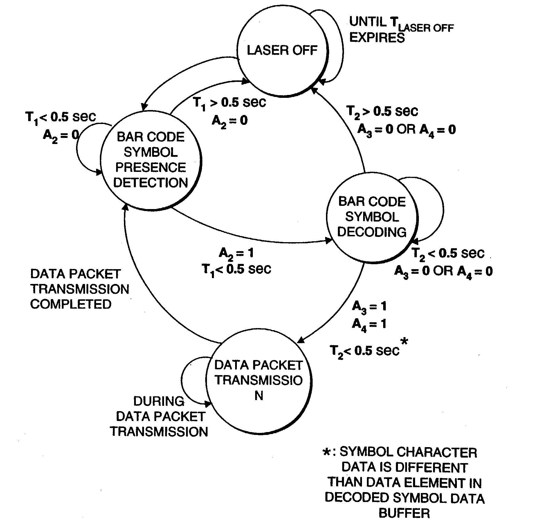
[0524] Having described the operation of the automatic hand-supportable bar code reading system of the second generalized system embodiment 460, it will be helpful to describe at this juncture the various conditions which cause state transitions to occur during its operation. In this regard, reference is made to FIG. 24 which provides a state transition diagram for the illustrative embodiment.

[0525] As illustrated in FIG. 24, the automatic hand-supportable bar code reading device of the present invention has four basic states of operation namely: object detection, bar code symbol presence detection, bar code symbol reading, and symbol character data transmission / storage. The nature of each of these states has been described above in great detail.

[0526] Transitions between the various states are indicated by directional arrows. Besides each set of directional arrows are transition conditions expressed in terms of control activation signals (e.g. A.sub.1, A.sub.2, A.sub.3 and A.sub.4)...


PUM


Abstract

Disclosed is an automatically-activated wireless code symbol reading system comprising a bar code symbol reading mechanism contained within a hand-supportable housing having a manually-activatable data transmission switch. During symbol reading operations, the bar code symbol reading mechanism automatically generates a visible laser scanning pattern for repeatedly reading one or more bar code symbols on an object during a bar code symbol reading cycle, and automatically generating a new symbol character data string in response to each bar code symbol read thereby. During system operation, the user visually aligns the visible laser scanning pattern with a particular bar code symbol on an object (e.g. product, bar code menu, etc.) so that the bar code symbol is scanned, detected and decoded in a cyclical manner. Each time the scanned bar code symbol is successfully read during a bar code symbol reading cycle, a new bar code symbol character string is produced, while an indicator light on the hand-supportable housing is actively driven. During the bar code symbol reading cycle, the user actuates the data transmission switch producing a data transmission control activation signal and enabling a currently or subsequently produced symbol character data string to be automatically selected and transmitted to the host system. By virtue of the present invention, automatically-activated hand-supportable bar code symbol readers are now able to accurately read, in an unprecedented manner, bar code symbols on bar code menus, consumer products positioned in crowded point-of-sale environments, and other objects requiring automatic identification and / or information access.

Description

RELATED CASES[0001] The present application is a continuation-in-part (CIP) of: application Ser. No. 09 / 204,176, filed Dec. 3, 1998, now U.S. Pat. No. 6,283,375; Copending application Ser. No. 08 / 979,974, filed Nov. 26, 1997, which is a Continuation of Ser. No. 08 / 690,677, filed Jul. 31, 1996, now U.S. Pat. No. 5,811,780, which is a Continuation of application Ser. No. 08 / 476,069, filed Jun. 7, 1995, now U.S. Pat. No. 5,591,953, which is a Continuation of application Ser. No. 08 / 147,833, filed Nov. 4, 1993, now U.S. Pat. No. 5,424,525, which is a Continuation of application Ser. No. 07 / 583,421, filed Sep. 17, 1990, now U.S. Pat. No. 5,260,553; application Ser. No. 08 / 890,586, filed Jul. 9, 1997, now U.S. Pat. No. 5,939,701; which is a Continuation of application Ser. No. 08 / 292,237, filed Aug. 17, 1994, now U.S. Pat. No. 5,808,285, which is a CIP of application Ser. No. 07 / 898,919, filed Jun. 12, 1992, now U.S. Pat. No. 5,340,973, also a CIP of application Ser. No. 07 / 761,123 filed ...

Claims


Application Information

Patent Timeline
Patent Type & Authority Applications(United States)
IPC IPC(8): G06K7/10G06K7/14
CPCB82Y15/00G06K2207/1012G06K7/10544G06K7/10564G06K7/10584G06K7/10594G06K7/10603G06K7/10663G06K7/10673G06K7/10693G06K7/10702G06K7/10792G06K7/10801G06K7/10811G06K7/10851G06K7/10861G06K7/10871G06K7/10881G06K7/10891G06K7/14G06K7/10
Inventor SCHMIDT, MARKRUSSELL, GARRETTWILZ, DAVID M. SR.BLAKE, ROBERTHUDRICK, DONALD T.COLAVITO, STEPHEN J.KNOWLES, C. HARRYROCKSTEIN, GEORGEZHU, XIAOXUNBONANNO, JOHNBYUN, SUNGXU, CONGWEIJIANG, MINGWANG, LINHU, MENGJIN, HONGJIANJI, MINGQINGSHI, SHAMEIAU, KA MANGIORDANO, PATRICK
Owner METROLOGIC INSTR
Why Eureka
Try Eureka