Locking apparatus
a technology of locking apparatus and locking rod, which is applied in the direction of mechanical control devices, keyhole guards, instruments, etc., can solve the problems of time and labor, many parts involved
- Summary
- Abstract
- Description
- Claims
- Application Information
AI Technical Summary
Benefits of technology
Problems solved by technology
Method used
Image
Examples
first embodiment
[0034] (First embodiment)
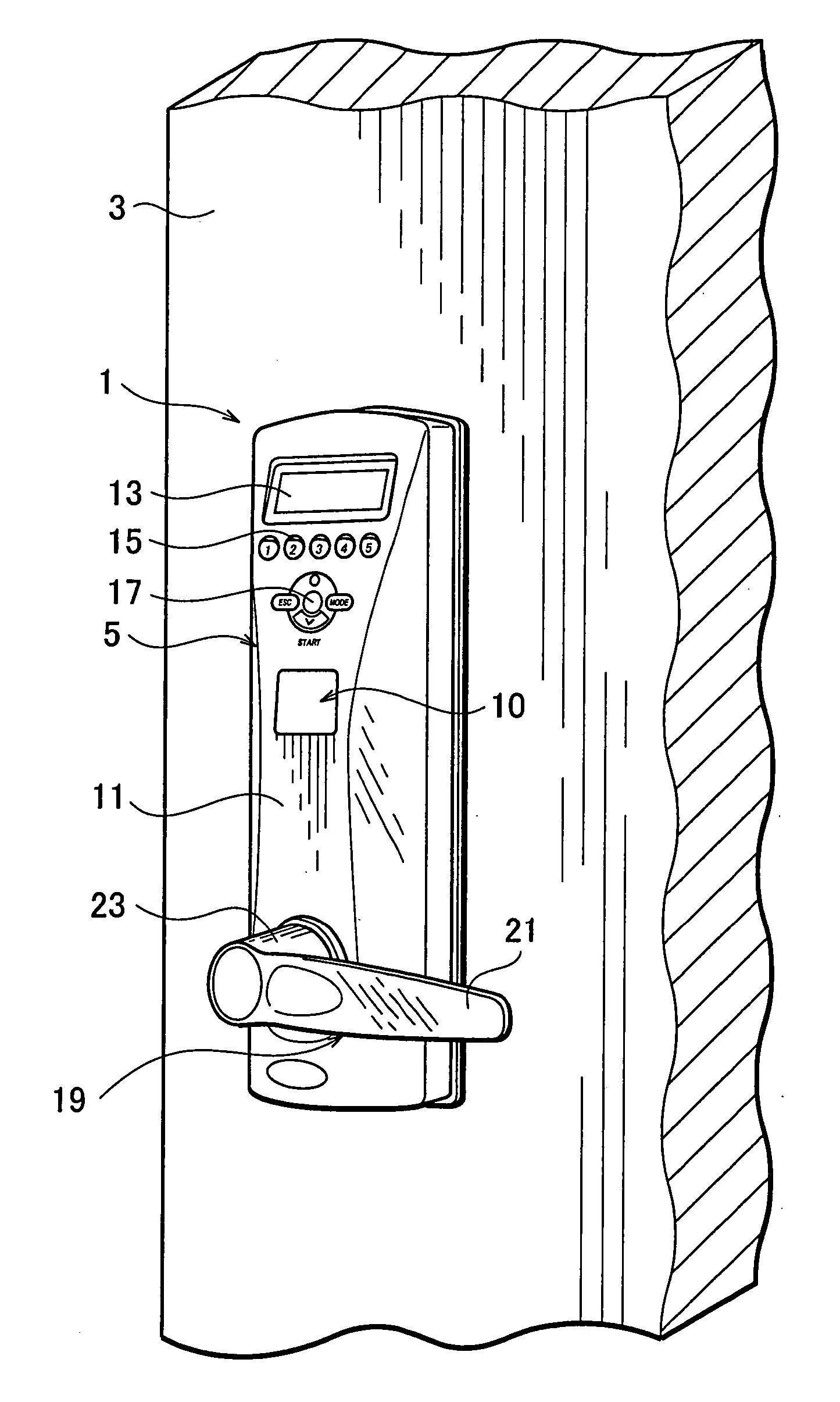
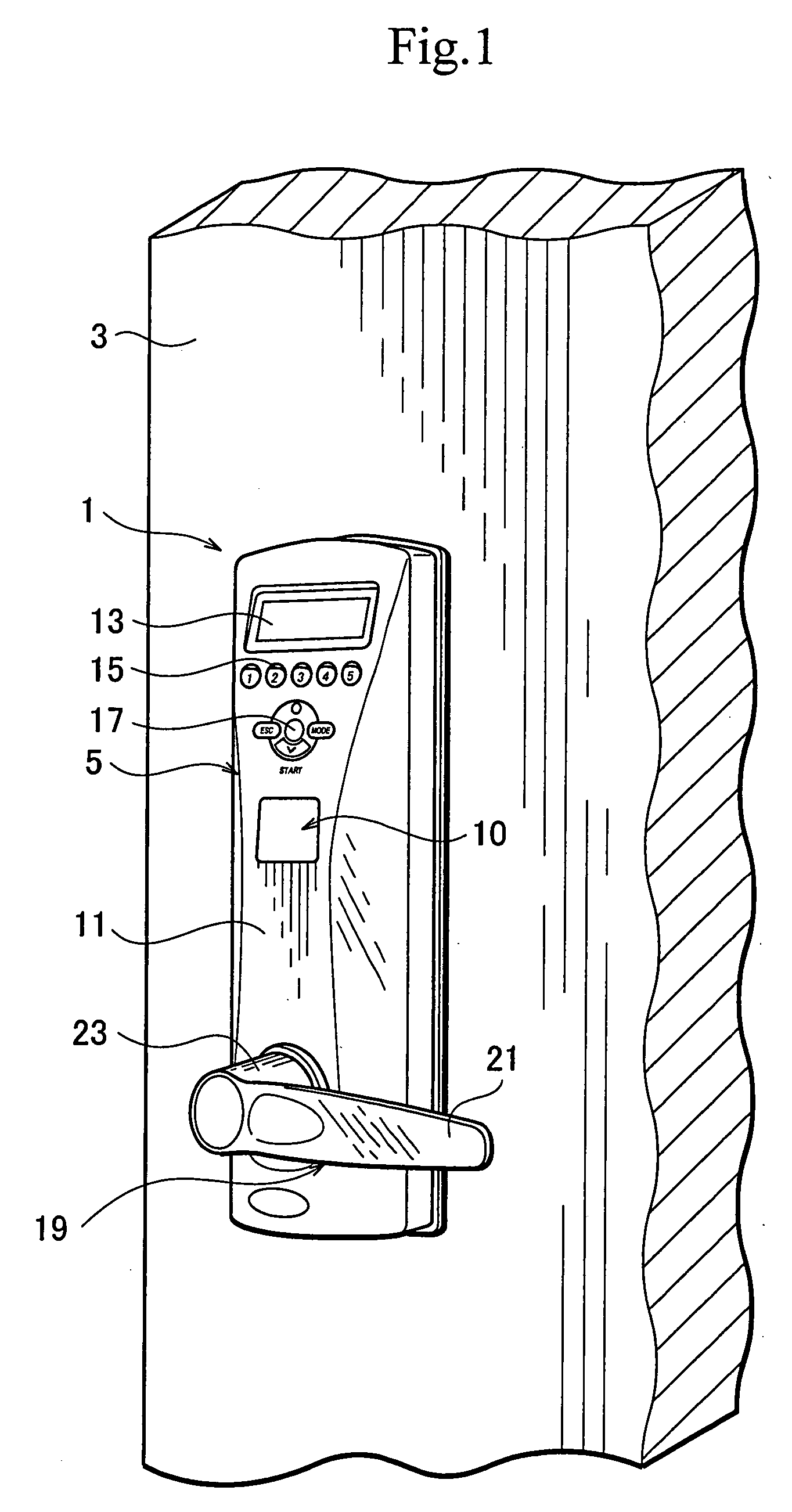
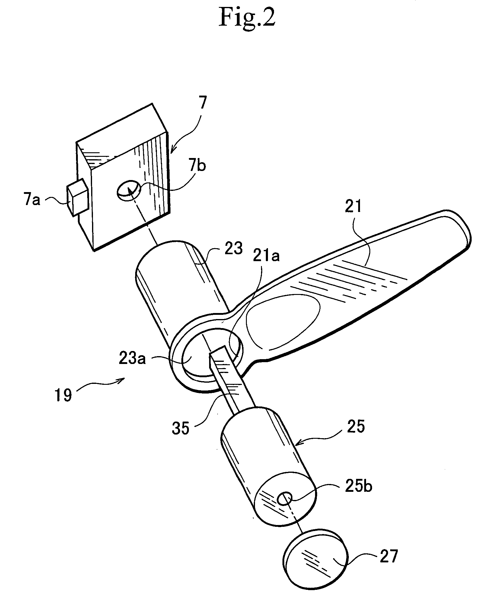
[0035] FIG. 1 is a perspective view partly showing a door with a locking apparatus according to the first embodiment of the present invention, FIG. 2 is an exploded view showing the locking apparatus of FIG. 1, and FIGS. 3A and 3B are sectional views showing a fingerprint verifier of the locking apparatus of FIG. 1 before and after inserting a finger into the verifier.
[0036] The locking apparatus 1 according to the first embodiment allows a user to optionally choose a usual locking / unlocking operation using a key or an easy locking / unlocking operation using no key. The locking apparatus 1 has an exterior unit 5 attached to the exterior side of a door 3. Inside the door 3, the locking apparatus 1 has a lock driver 7 to lock and unlock the door 3. The locking apparatus 1 also has a fingerprint read / verify unit 9 forming a part of a biometric verifier 10. When a person wants to lock or unlock the door 3, the person puts a finger on the read / verify unit 9. Then,...
second embodiment
[0064] (Second embodiment)
[0065] FIG. 6 is a circuit diagram showing a locking apparatus according to a second embodiment of the present invention, and FIG. 7 is a sectional view partly showing a key cylinder of the locking apparatus of FIG. 6. The second embodiment of FIGS. 6 and 7 is based on the first embodiment of FIGS. 1 to 5, and therefore, like parts are represented with like reference marks throughout the drawings, and the explanation of like parts will not be repeated.
[0066] The second embodiment employs a buzzer or an alarm 34 to give an alarm when the key 31 or a foreign object is inserted into the opening 25b of the key cylinder 25 to manually operate the lock driver 7. In FIG. 6, the second embodiment connects an alarm power supply circuit or a buzzer power supply circuit to the fingerprint read / verify unit 9 that is also connected to the power supply circuit of FIG. 4 of the first embodiment.
[0067] The buzzer power supply circuit includes the buzzer 34, a detector swit...
PUM
 Abstract
Description
Claims
Application Information
 - R&D
- Intellectual Property
- Life Sciences
- Materials
- Tech Scout
- Unparalleled Data Quality
- Higher Quality Content
- 60% Fewer Hallucinations
Browse by: Latest US Patents, China's latest patents, Technical Efficacy Thesaurus, Application Domain, Technology Topic, Popular Technical Reports.
© 2025 PatSnap. All rights reserved.Legal|Privacy policy|Modern Slavery Act Transparency Statement|Sitemap|About US| Contact US: help@patsnap.com


