
Speed measurement device with statistic gathering capability

a speed measurement and statistic gathering technology, applied in the field of speed measurement devices, can solve the problems of large volume of speed measurement devices designed for use by law enforcement officers, requiring external power sources, and not being well suited to sporting events

Inactive Publication Date: 2004-02-12
BUSHNELL
View PDF0 Cites 13 Cited by
  • Summary
  • Abstract
  • Description
  • Claims
  • Application Information

AI Technical Summary

Benefits of technology

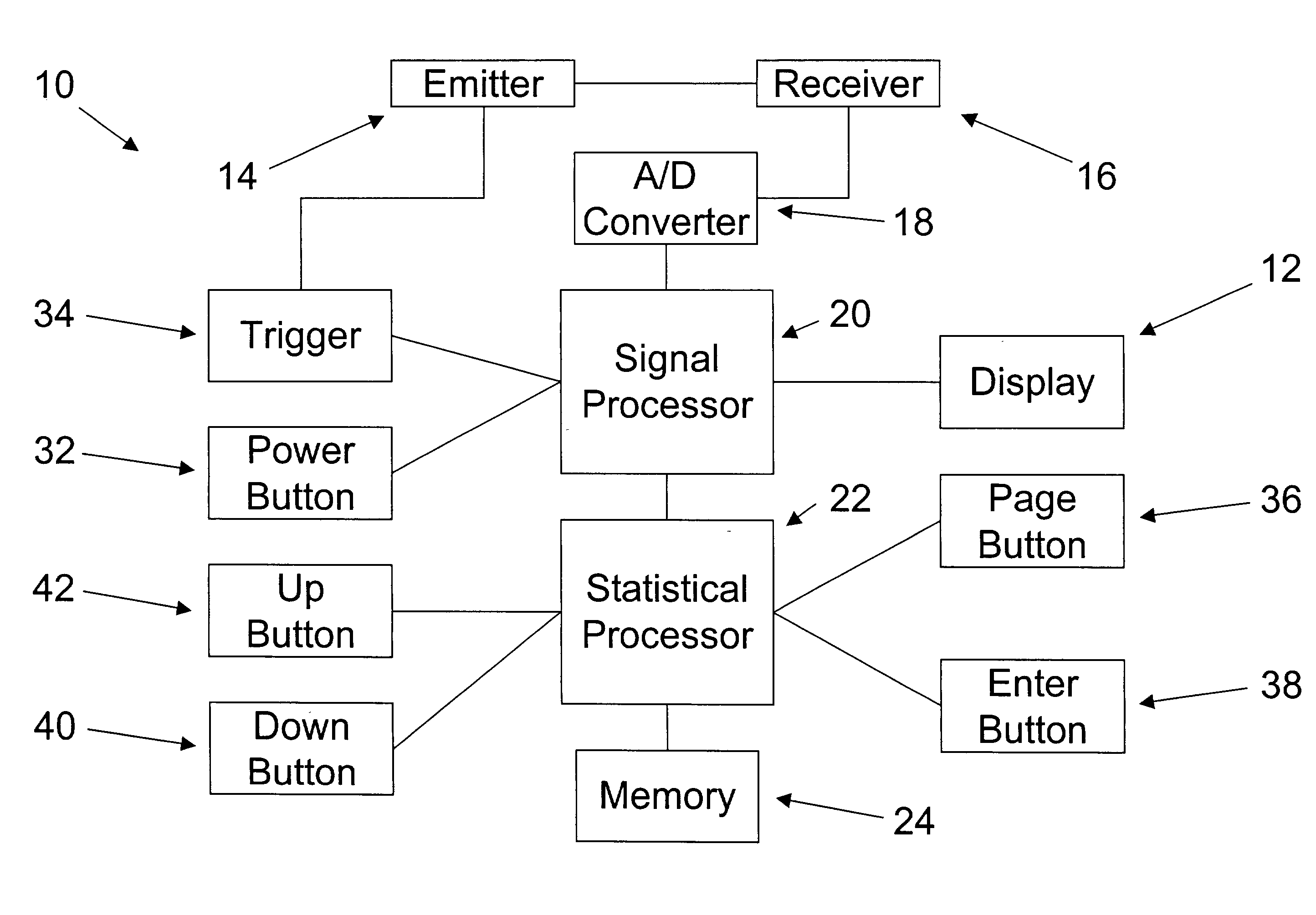
[0012] The radar emitter and the radar receiver are preferably mounted behind a front panel of the housing. This configuration allows the user to direct the emitted radar waves toward and receive the received radar waves reflected from the target by pointing the device at the target. The radar emitter and the radar receiver are preferably electrically coupled allowing the radar receiver to detect the Doppler Shift and generate analog signals representative of the Doppler Shift.

Problems solved by technology

Sports enthusiasts often wish to use these devices at sporting events to track the speed of thrown or hit balls, but devices designed for use by law enforcement officers are typically not well suited for use at sporting events, for a number of reasons.
First, speed measuring devices designed for use by law enforcement purposes are typically bulky and may require external power sources.
Second, these devices are specifically designed to detect the speed of large vehicles and may not be able to efficiently detect the speed of small objects, such as baseballs.
In recent years, speed measurement devices have been modified to be more useful at sporting events allowing them to detect the speed of baseballs; however, they are not capable of collecting statistics.

Method used


Image

  • Speed measurement device with statistic gathering capability
  • Speed measurement device with statistic gathering capability
  • Speed measurement device with statistic gathering capability

Examples


Embodiment Construction

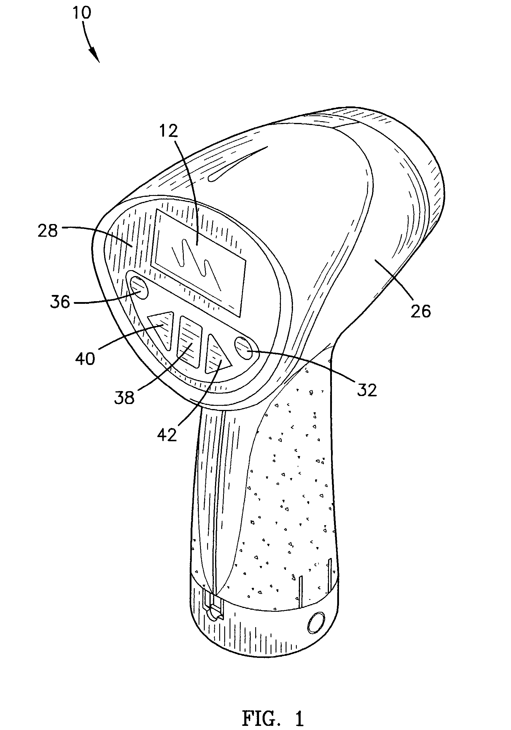
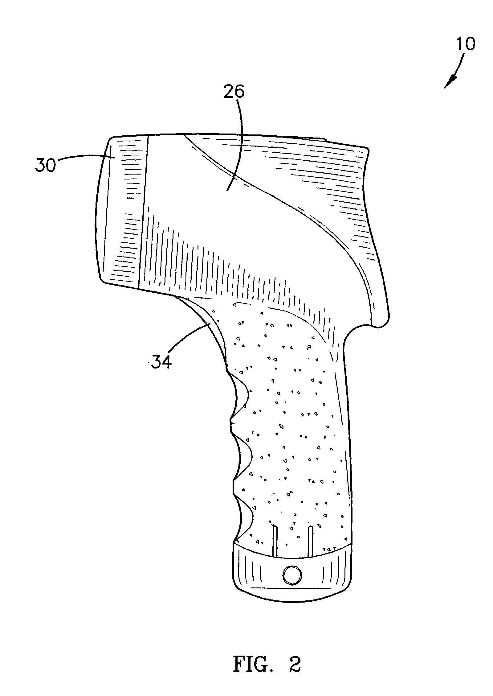
[0024] Referring to FIGS. 1-3, a radar speed measurement device 10 is shown constructed in accordance with a preferred embodiment of the present invention. The device 10 uses radar to measure speed by emitting radar waves at a target, such as a baseball, a softball, a football, or other object. As the radar waves are reflected by the target, they undergo a frequency shift. This phenomenon is commonly known as a Doppler Shift. The magnitude of the Doppler Shift can be used to calculate a target speed, which is the speed of the target, relative to the device 10.

[0025] The device 10 emits emitted radar waves at a specific emission frequency and receives received radar waves at a slightly different reception frequency, depending upon the target speed. The emission frequency is preferably between 20 Giga-Hertz and 40 Giga-Hertz, commonly known as a K-band. For example, the emission frequency may be 24.125 Giga-hertz or 24.150 Giga-Hertz.

[0026] The device 10 broadly comprises a radar emit...


PUM


Abstract

A radar speed measurement device (10) comprising a display (12) for displaying a target speed, a radar emitter (14) for emitting radar waves toward a target, a radar receiver (16) for receiving radar waves reflected from the target, an analog to digital converter (18) for producing digital signals associated with the radar waves, and a signal processor (20) for determining the target speed by analyzing the digital signals. The device (10) can also calculate statistics associated with the target and further comprises a statistical processor (22) for calculating the statistics. The device (10) can operate in either of two modes. A speed mode is preferably used to determine the target speed, when the target is a race car or any other object. A baseball statistics mode is preferably used to determine the target speed, when the target is a baseball thrown by a pitcher.

Description

[0001] 1. Field of the Invention[0002] The present invention relates to speed measurement devices. More particularly, the present invention relates to a radar speed measurement device that can calculate and store statistical information.[0003] 2. Description of Prior Art[0004] Most radar speed measurement devices are designed to be used by law enforcement officers to determine vehicle speeds in an effort to monitor traffic flow and enforce traffic laws. Sports enthusiasts often wish to use these devices at sporting events to track the speed of thrown or hit balls, but devices designed for use by law enforcement officers are typically not well suited for use at sporting events, for a number of reasons. First, speed measuring devices designed for use by law enforcement purposes are typically bulky and may require external power sources. Second, these devices are specifically designed to detect the speed of large vehicles and may not be able to efficiently detect the speed of small obj...

Claims


Application Information

Patent Timeline
Patent Type & Authority Applications(United States)
IPC IPC(8): A63B71/06G01S13/58
CPCA63B71/06A63B2243/0004G01S13/585A63B2243/007A63B2243/0025A63B2102/18A63B2102/182
Inventor VERMILLION, JORDAN
Owner BUSHNELL
Learn More